8
FLAME SCANNERS
For a complete system, choose one of each of the following:
- Chassis - Flame Detector
- Programmer Module - Wiring Base
- Amplifier Module
Accessories
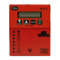
ED510 Two line by 16 character, back lit LCD display with keypad.
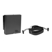
ED580-2, -4, -8 Remote display cable with RJ45 connection in 2, 4 or 8 foot long lengths. To be used with the appropriate daughter
board.
EC485 RS232 to RS485 converter with power supply and RJ12 jack.
UC485 USB to RS485 converter. Supplied with USB cable.
SMDK-1004 Serviceman’s display kit used for diagnosing MicroM system. Consists of ED510 equipped with back plate, MED
daughter board and ED580-4.
129-145-1, -2, -3 ED510 remote display mounting kit with 4’, 8’ or 2’ cable respectively. Provides NEMA 4 protection.
IT1000 Monitoring device using cellular networks. Provides various reporting methods
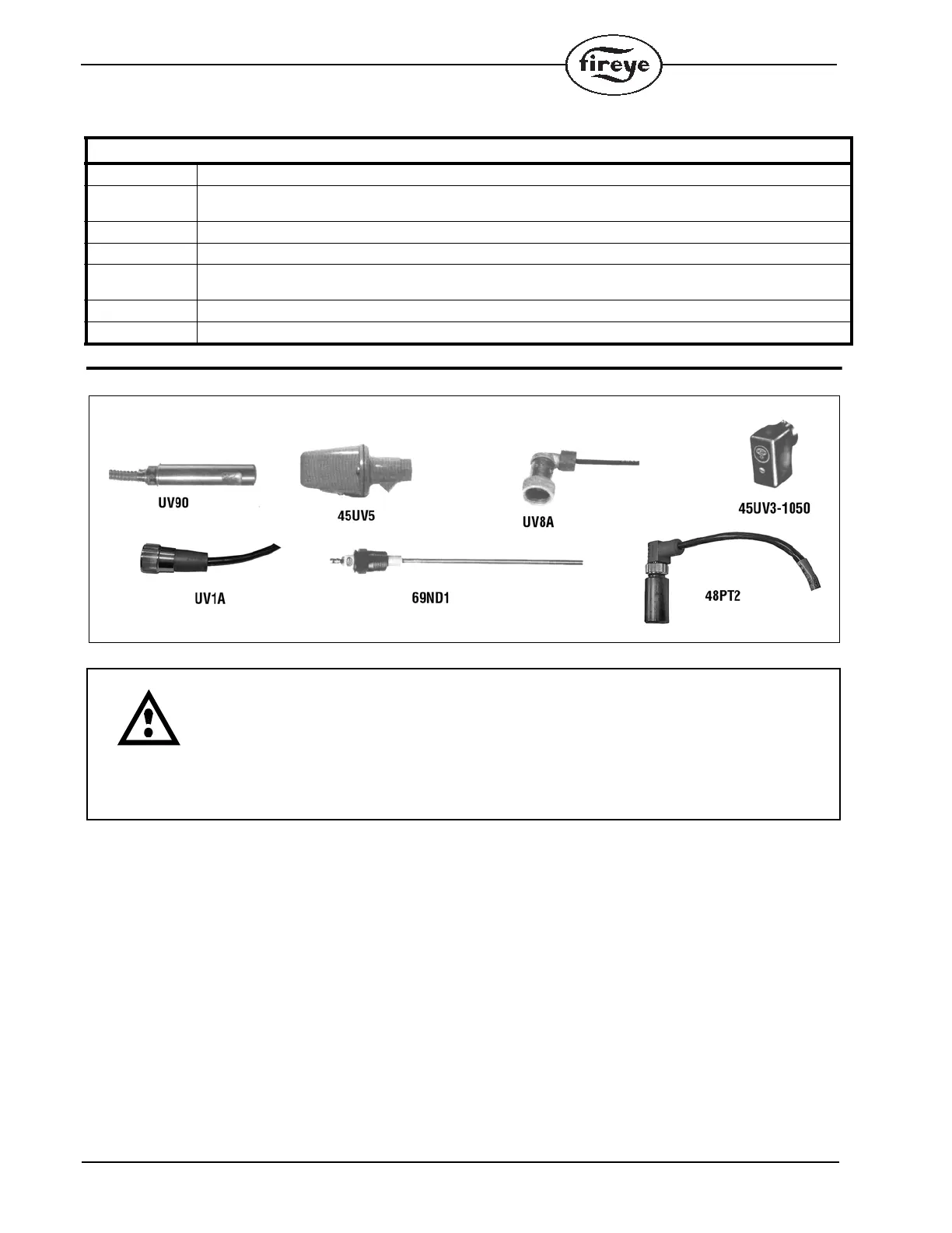
CAUTION: The UV1A, UV2, UV8A, UV90 and 45UV3 ultra-violet flame scanners and asso-
ciated amplifier modules are non self-checking UV systems and should be applied only to
burners that cycle often (e.g.: a minimum of once per 12 hours) in order for the safety check-
ing circuit to be exercised. If component checking is required during burner operation for
constantly fired burners, utilize the self-checking ultra-violet flame scanners (45UV5) with
associated amplifier module (MEUVS1, MEUVS4) or the infrared flame scanner (48PT2)
with associated AutoCheck amplifier (MEIR1, MEIR4).
 Loading...