40
Wiring Arrangements
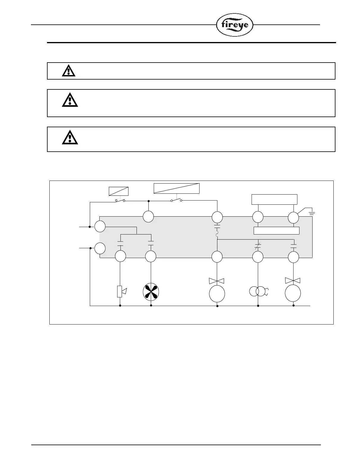
FIGURE 6. WIRING ARRANGEMENT FOR PILOT IGNITED BURNERS USING MEP100 AND MEP200 SERIES PROGRAMMERS
IMPORTANT: Use moisture resistant wire rated 90°C minimum.
CAUTION: When powered, 560 VAC across S1, S2 with MEUV4, MEUV1, MEUVS4 and
MEUVS1; 260 VAC across S1, S2 with MERT4 and MERT1.
CAUTION: Control wiring procedures which deviate from those shown in the diagrams
may bypass safety functions designed in the control. Check with the Fireye Representative
before deviating from the recommended wiring diagrams.
PV
MV
S1
7
3
5
4
1
A
S2
INTERMITTENT
MAIN VALVE
BLOWER MOTORALARM
8
120VAC
50/60Hz
T
P
FLAME AMPLIFIER
SPARK
KL
KF-2
KF-1
PILOT VALVE
IGNITION
*
H
N
2
* For intermittent ignition, connect to terminal 3
FLAME
SCANNER
OR
CONTACTOR
OPERATING
CONTROLS
KB
KA
(WATCHDOG)
AIR FLOW
INTERLOCK
F1
6
FLAME
ROD
ONLY
 Loading...