NO.
Description Qty.
82
83
84
85
86
87
88
89
90
91
92
93
94
95
96
97
98
99
100
101
102
103
104
105
106
107
108
109
110
111
112
113
114
115
116
117
118
119
120
121
122
123
124
125
126
127
128
129
130
131
399715808
399715809
399715810
399715811
399715812
399715813
399715814
399715815
399715816
399715817
399715818
399715819
399715820
399715821
357723501
357723502
399715824
399715825
399715826
399715827
399715828
399715829
399715830
399715831
399715832
399715833
399715834
399715835
399715836
399715837
399715838
399715839
399715840
399715841
399715842
399715843
399715844
399715845
399715846
336723604
357723544
330723555
399715850
399715851
399715852
399715853
393713040
399715855
399715856
399715857
Part Number
Pillar
Start Motor combination
Flange bolt M8 × 105
Ignition coil
Flange bolt M6 × 45
Flange bolt M6 × 15
Vent chamber cover
Vent chamber cover pad
Cross screw M3 × 8
Stopper plate
check valve slice
Shaped bolt
Left guide
Oil seal 35 × 48 × 8
Oil pressure alarm
Hexagonal plug
Crankcase assembly
Ignition coil (right)
Leading broad assembly
Control module
Flywheel assembly
Cooling fan
Fan block
Flange nut M20 × 1.5
Fan cover assembly
Cover
Gasoline pump
Screen
Screw
Oil cooler
Oil pipe
Screw
Clamp Ø15 × 12
Quick oil drain pipe
Oil drain bolt (1006)
Pin Ø12 × 20
Bolts M6 × 32
Inlet gasket
Cylinder cover
Cylinder cover (right)
Wind scooper, Right
Clamp Ø9.4 × 8
Negative pressure tube
Cylinder cover (right)
Bolt M8 × 35
4
1
2
1
4
9
1
1
1
1
1
4
1
1
1
1
1
1
1
1
1
1
1
1
1
1
1
1
1
6
1
1
4
1
1
2
4
4
1
1
4
4
2
2
1
1
1
1
1
4
English Customer Service: 1-844-FIRMAN1
34
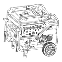
Parts Diagrams - Parts Lists - Wiring Diagram
NO.
Description Qty.
399715858
399715859
399715860
399715861
399715862
399715863
399715864
Part Number
8
4
1
1
1
1
1
132
133
134
135
136
137
138
Cylinder cover assembly (left)
Oil drain bolt M12 × 1.25 × 15
Oil drain bolt washer 12 × 20 × 2
Self-tapping screw ST5.5 × 13
Oil cooler supporting plate
Valve lock clamp
Screw M3 × 8
Electromagnet assembly
Screw M4 × 20
Idle rod
Flange nut M4
Support spring, Electromagnet
 Loading...