Smoke Detectors (continued)
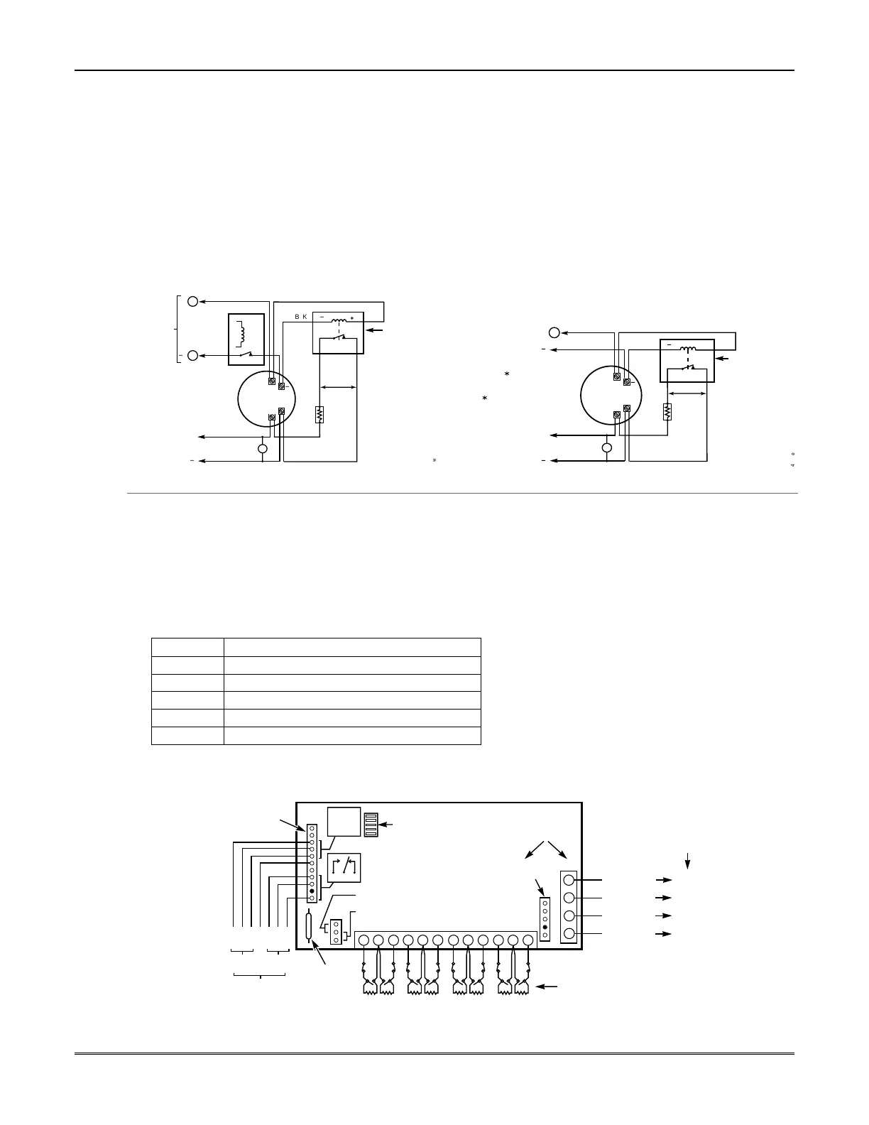
4-Wire Smoke Detectors
3. Connect 4-wire smoke detectors (up to 16, depending
on detector current draw) to any zone from 2-8 as
shown below. This control does not automatically reset
power to 4-wire smoke detector zones, so you must use
a relay (e.g., 4204, 4229), or on-board trigger to reset
power (also required for fire verification). Do this by
programming the designated relay/trigger as zone type
54 (fire zone reset); see On-Board Trigger section for
other information.
NOTE: Maximum current on trigger 17 is 100mA.
Notes
• Do not use 4-wire smoke detectors on zone 1.
Figure 7. 4-Wire Smoke Detector Connections
+
+
2000
OHMS
EOLR
HEAT
DETECTOR
RED
EOL
POWER
SUPERVISION
RELAY MODULE
A77-716B.
USE N.O.
CONTACT,
WHICH CLOSES
WHEN POWER
IS APPLIED.
VIOLET
AUX PWR
OUTPUT
TERMINALS
5
4
_
_
+
_
BLK
_
+
4_wiresmk-007-V0
TO ZONE TERM. ( )
TO ZONE TERM. ( )
RELAY
CONTACT OPENS
MOMENTARILY UPON
FIRE ALARM RESET
PROGRAM
RELAY
AS ZONE
TYPE 54
(FIRE ZONE
RESET)
4-WIRE SMOKE
OR COMBUSTION
DETECTOR
N.C.
N.O.
+
2000
OHMS
EOLR
HEAT
DETECTOR
RED
VIOLET
AUX PWR
5
_
+
_
BLK
_
+
4_wiresmk-008-V0
4-WIRE SMOKE
OR COMBUSTION
DETECTOR
( )
( )
+
_
TO ZONE TERM. ( )
TO ZONE TERM. ( )
TO OUTPUT 17
PROGRAM OUTPUT 17
FOR "OUT NORM
LOW" = YES IN 79 MENU
MODE AND AS ZONE
TYPE 54 IN
80 MENU MODE
EOL
POWER
SUPERVISION
RELAY MODULE
A77-716B.
USE N.O.
CONTACT,
WHICH CLOSES
WHEN POWER
IS APPLIED.
N.O.
4-Wire Smoke Detector Using Relay for Power Reset 4-Wire Smoke Detector Using Output 17 for Power Reset
4219/4229 Expansion Zones
1. Connect each module to the control’s keypad
terminals.
2. Assign each module a unique device address (07-11)
using its DIP switches. Device addresses determine
the zone numbers being used, as shown in the
following table.
Expander Module Addresses
For Zones…Set Module to Device Address…
09-16 07 (not available if zone-doubling enabled)
17-24 08
25-32 09 (FA168CPS)
33-40 10 (FA168CPS)
41-48 11 (FA168CPS)
3. Connect sensors to the module’s loops.
4. If using relays with the 4229, connect the desired
field wiring to the unit's relay contact terminals.
Notes
• Supports expansion zones (NO or NC) using
4219/4229 Zone Expander Modules as follows:
FA168CPS: Up to 40 expansion zones using up to
five Zone Expander Modules.
FA148CP: Up to 16 expansion zones using up to
two Zone Expander Modules.
• Use 1000 ohm end-of-line resistors at the end of
loops connected to the 4219/4229 modules. (End-
of line resistors used on the control terminals are
2000 ohms.)
•
Expansion zones have normal response time
(300–500 msec), except zone connected to each
module’s loop “A,” which can be set for fast
response (10–15 msec).
BRN
GRN
BLK
(–) GROUND
RED
(+) 12VDC
YEL
4
3
2
1
ZONES
A
B
C
D
F
GH
DIP SWITCH
FOR SETTING ADDRESS
AND ZONE "A" RESPONSE
TAMPER JUMPER POSITION
4229 IN CABINET
(NOT TAMPER)
4229 REMOTE
(TAMPER PROTECTED)
TB1
4229
TB2
WHT
GRY
VIO
BLK
YEL
ORG
NO
NC
C
GND
NO
NC
C
RLY
1
RLY
2
RELAYS OFF
RELAY
CONNECTOR
RELAY
2
RELAY
1
(TERM 6)
(TERM 4)
(TERM 5)
(TERM 7)
NO C NC
TERMINALS ON
CONTROL PANEL
1
2
3
4
DATA OUT (>)
TO CONTROL
DATA IN (<)
FROM
CONTROL
5
8
11
REED
(TAMPER)
SWITCH
2
E
1
3
4 6
7
9
10
12
TERMINATE EACH
PROGRAMMED ZONE
WITH 1000 OHM (1K)
END-OF-LINE RESISTOR
(EACH ZONE'S MAX.
LOOP RESISTANCE
300 OHMS + EOL)
4-PIN CONSOLE PLUG
EITHER OR BOTH CAN BE USED
4229-002-V0
Figure 8. Wiring Connections, 4219 & 4229 (4229 shown)
Mounting and Wiring the Control
2-7