Wiring to Keypads
1. Connect keypads to the control’s keypad terminals as
shown on the Summary of Connections diagram.
Determine wire size using the Wire Run Chart below.
2. Set keypad addresses. Refer to the address setting
instructions included with the keypads and set each
keypad device address according to the chart at right.
3. Program the keypad addresses, partition
assignments and sound options in data fields *190-
*196.
NOTE: Each keypad must be assigned a unique
address, starting at address 16. Keypads
programmed with the same address will give
unpredictable results.
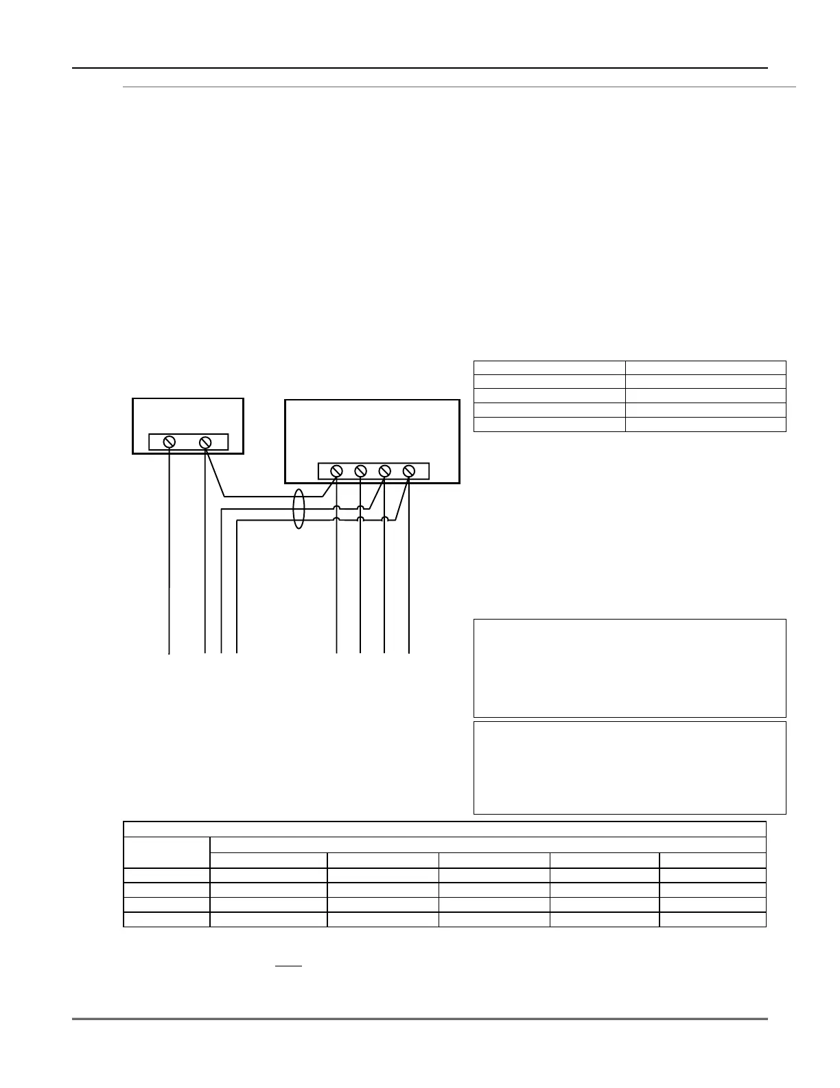
Supplementary Power (optional)
1. Connect as shown. Be sure to connect the negative (–)
terminal on the power supply unit to terminal 4
(AUX –) on the control.
+
–
+
456 7
SUPPLEMENTARY
POWER SUPPLY
–
CONTROL TERMINAL STRIP
AUX.
AUX. DATA
IN
DATA
OUT
IMPORTANT:
MAKE THESE
CONNECTIONS
DIRECTLY TO
SCREW
TERMINALS AS
SHOWN.
TO KEYPAD RED WIRE
TO KEYPAD BLK WIRE
TO KEYPAD YEL WIRE
TO KEYPAD GRN WIRE
TO KEYPAD BLK WIRE
TO KEYPAD RED WIRE
TO KEYPAD GRN WIRE
TO KEYPAD YEL WIRE
supp_pwr_supply-V0
Figure 4. Using a Supplementary Power Supply
Notes
• Fixed-Word Display: FA215KP, FA260KP
• Alpha Display: FA560KP; Voice Keypad: FA560VKP
• Keypad/Transceiver: FA260RF
• AUI: Up to two Symphony FA800KP (see note
below) or FA700KP Touch Screen keypads
• The system supports up to 8 keypads, which can be
assigned to partitions in any combination
(see program fields *190-*196).
• For single 4-wire runs, determine the current
drawn by all units, then refer to the Wiring Run
chart to determine the maximum length that can
be safely used for each wire size.
• Use supplementary power if the control’s aux. power
load for all devices exceeds 600mA.
Suggested power supply: AD12612
Keypad Addresses
Keypad Address Keypad Address
no. 1 16** no. 5 20
no. 2 17 no. 6 21
no. 3 18 no. 7 22
no. 4 19 no. 8 23
** The first keypad is address 16, which is always
enabled and set for partition 1 with all sounds on.
AUI NOTES:
•
••
• Use of AUI is independent from standard keypads and
does not affect the number of standard keypads the
system can support.
•
••
• AUI keypads must be set for either address 1 or address
2, depending on which unit is enabled in field *189.
•
••
• To ensure proper AUI device operation, connect only to
controls having microprocessor version 3.0 or higher, and
use AUI devices with the following rev levels: FA700KP
series use version 1.0.9 or higher; FA800KP (Symphony)
series use version 1.1.175 or higher.
U
L
Use a UL Listed, battery-backed supply for UL
installations. The battery supplies power to these
keypads in case of AC power loss.
The battery-backed power supply should have
enough power to supply the keypads with the UL
required minimum standby power time.
Keypads powered from supplies that do
not have a backup battery will not function if AC
power is lost. Make sure to power at least one keypad
in each partition from the control’s auxiliary power
output.
Wire Run Chart For Devices* Drawing Aux Power From The Control (12V+ & 12V–)
Wire
TOTAL CURRENT DRAWN BY ALL DEVICES CONNECTED TO A SINGLE WIRE RUN
Size 50 mA or less 100 mA 300 mA 500 mA 600 mA
#22 900 ft (274m) 450 ft (137m) 150 ft (46m) 90 ft (27m) 75 ft (23m)
#20 1400 ft (427m) 700 ft (213m) 240 ft (73m) 140 ft (43m) 120 ft (37m)
#18 1500 ft (457m) 1100 ft (335m) 350 ft (107m) 220 ft (67m) 170 ft (52m)
#16 1500 ft (457m) 1500 ft (457m) 550 ft (168m) 350 ft (107m) 270 ft (82m)
* Includes Keypads, RF Receivers, Zone Expander/Relay Units, FA4285/FA4286 Phone Module, and Long Range Radio.
Maximum wire lengths for any device that is homerun to the control can also be determined from the Wiring Run Chart, based on
the current draw of that device alone
.
The length of all wire runs for both partitions combined must not exceed 1500 feet (457m) when unshielded quad conductor cable is
used (750 feet if shielded cable is used). This restriction is due to the capacitive effect on the data lines when quad cable is used.
Mounting and Wiring the Control
2-3