3
The Mounting Bracket:
T
o remove the mounting bracket from the Alarm
base, hold the Alarm base firmly and twist the
mounting bracket counter
clockwise. The mounting
bracket installs onto the junction box. It has a
variety of screw slots to fit most boxes.
The Power Connector:
The power connector plugs into a power input block
on the Alarm. It supplies the unit with AC power
.
• The black wir
e is “hot.”
• The white wire is neutral.
• The orange wire is used for interconnect.
If you need to remove the power connector, turn
POWER OFF first. Insert a flat scr
ewdriver blade
between the power connector and the security tab
inside the power input block. Gently pry back the tab
and pull the connector free.
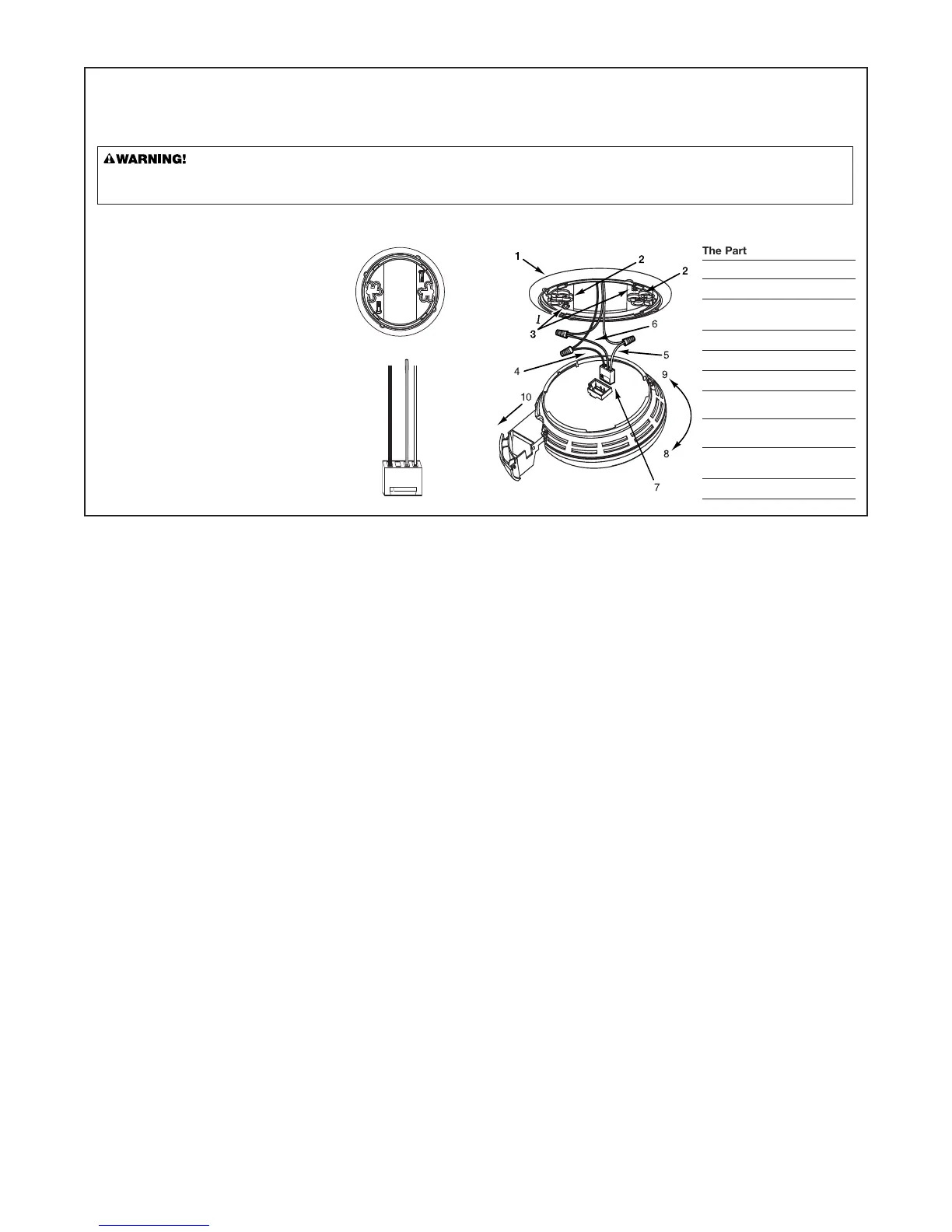
The Par
ts of This Unit
1 Mounting Bracket
2 Mounting Slots
3
Locking Pins (break out of
bracket)
4 Hot (Black) AC Wire
5
Neutral (White) AC Wire
6
Interconnect (Orange) Wire
7 Quick-Connect Power
Connector
8
Turn this way to remove
from bracket
9 Turn this way to attach to
bracket
10 Slide-Out Battery Drawer
HOW TO INST
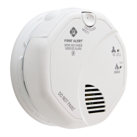
ALL THIS SMOKE/CO ALARM
THE PARTS OF THIS ALARM
This Smoke/CO Alarm is designed to be mounted on any standar
d wiring junction box up to a 4-inch (10 cm) size, on either the ceiling or wall (if allowed
by local codes). Read “Where to Install This Alarm” and “Where This Alarm Should Not Be Installed” before you begin installation.
T
ools you will need: • Needle-nose pliers or utility knife
• Standar
d flathead screwdriver
• W
ire strippers.
Make sur
e the Alarm is not receiving excessively noisy power. Examples of noisy power could be major appliances on the same circuit, power
from a generator or solar power, light dimmer on the same circuit or mounted near fluorescent lighting. Excessively noisy power may cause
damage to your Alar
m.