LOCKING FEATURES
The locking featur
es are designed to discourage unauthorized removal of the batteries or Alarm. It is not necessary to activate the locks in
single-family households where unauthorized battery or Alarm removal is not a concern.
These Alarms have two separate locking featur
es: one to lock the battery compartment, and the other to lock the Alarm to
the mounting bracket. Y
ou can choose to use either feature independently, or use them both.
Tools you will need: • Needle-nose pliers • Standard Flathead screwdriver.
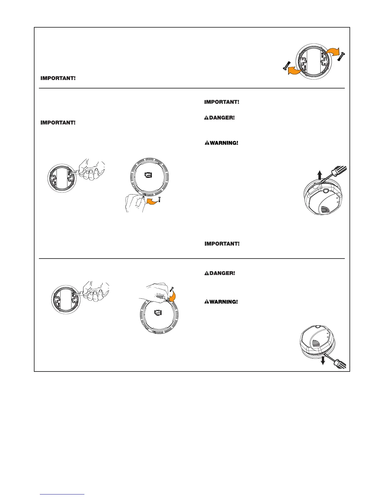
Both locking features use locking pins, which are molded into the mounting bracket. Using needle-nose pliers, remove
one or both pins fr
om the mounting bracket, depending on how many locking features you want to use.
To permanently remove either lock, insert a flathead screwdriver between the locking pin and the lock, and pry the pin out of the lock.
TO LOCK THE BATTERY COMPARTMENT
Do not lock the battery compartment until you have installed the
battery and tested the battery back-up.
1. Push and hold Test/Silence button until the alarm sounds.
If the unit does not alar
m during testing, DO NOT lock the battery
compartment! Install a new battery and test again. If the Alarm still
does not alar
m, replace it immediately.
2.
Using needle-nose pliers, detach one locking pin from the mounting
bracket.
3. Push the locking pin through the hole near the battery drawer on
the back of the Alarm.
TO UNLOCK THE BATTERY COMPARTMENT
Once the Alarm is installed, you must disconnect it from the AC power
befor
e unlocking the battery compartment.
ELECTRICAL SHOCK HAZARD. Turn off the power to the area where
the Alar
m is installed before removing it from the mounting bracket.
Failur
e to turn off the power first may result in serious electrical
shock, injury or death.
Always dischar
ge the branch circuit before servicing an AC or AC/DC
Alar
m. First, turn off the AC power at the circuit breaker or fuse box.
Next, remove the battery from Alarms with battery back-up. Finally,
pr
ess and hold the Test/Silence button for 5-10 seconds to discharge
the branch cir
cuit.
1. Remove the Alarm from the mounting bracket.
If the unit is locked to the bracket, see the
section “T
o Unlock the Mounting Bracket.”
2. Disconnect the power connector by gently
prying it away from the back of the Alarm.
3. Insert a flathead screwdriver under the head
of the locking pin, and gently pry it out of the
battery compartment lock. (If you plan to
relock the battery compartment, save the
locking pin.)
4. To relock the battery compartment, close the battery door and
reinsert locking pin in lock.
5. Reconnect the power connector to the back of the Alarm, reattach
the Smoke Alarm to the mounting bracket, and restore the power.
When replacing the batteries, always test the Alarm before relocking the
battery compartment.
TO UNLOCK THE MOUNTING BRACKET
ELECTRICAL SHOCK HAZARD. Turn off the power to the area where
the Alarm is installed before removing it from the mounting bracket.
Failure to turn off the power first may result in serious electrical
shock, injury or death.
Always discharge the branch circuit before servicing an AC or AC/DC
Alar
m. First, tur
n of
f the AC power at the circuit breaker or fuse box.
Next, r
emove the batter
y from Alarms with battery back-up. Finally,
press and hold the Test/Silence button for 5-10 seconds to discharge
the branch circuit.
1. Insert a flathead screwdriver between the
mounting bracket pin and the mounting
bracket.
2. Pry the Alarm away from the bracket by
turning both the screwdriver and the Alarm
counterclockwise (left) at the same time.
TO LOCK THE MOUNTING BRACKET
1. Using needle-nose pliers, detach one locking pin from mounting
bracket.
2.
Insert the locking pin into the lock located
opposite from the battery drawer as shown
in the diagram.
3.
When you attach the Alarm to the mounting bracket, the locking
pin’
s head will fit into a notch on the bracket.
5