HEIGHT ADJUSTABLE TABLE
ASSEMBLY INSTRUCTIONS
RANGE
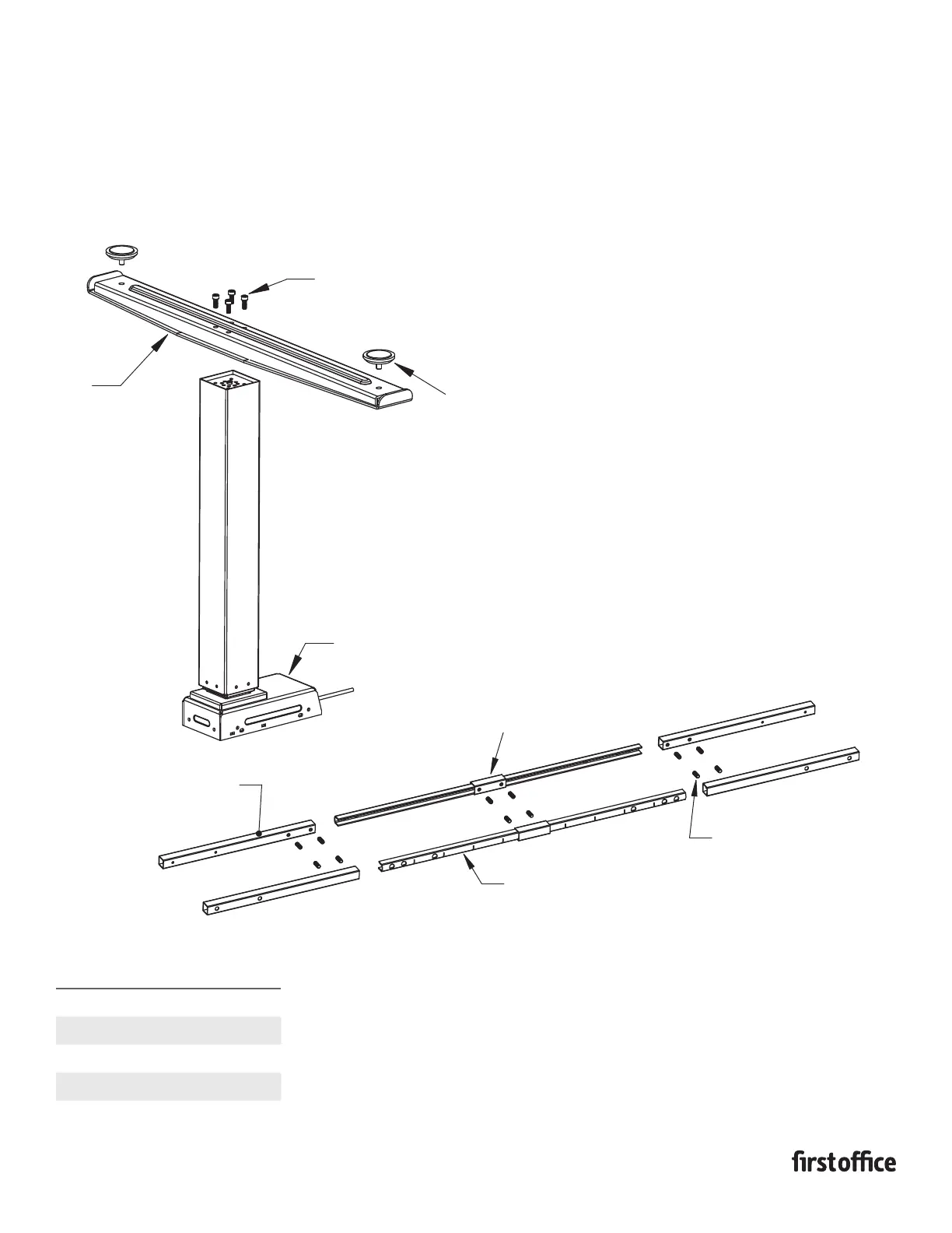
1. Assemble the foot to the leg column with 4 M6x15 hex
socket cap screws.
2. Install the leveling glides into the bottom of the foot.
3. Repeat above steps to create a “LH” and a “RH”
leg assembly.
INSTRUCTION SHEET #2586INS
PART #1730739
TOP SIZES
SPANNER BAR
INSERTION DEPTH
48" 20.125"
54" 20.125"
60" 16"
66" 14.5"
72" 11.75"
M6X15 HEX SOCKET
HEAD CAP SCREW
LEVELING GLIDES
HEIGHT ADJUSTABLE
LEG COLUMN
FOOT
RH FOOT
ASSEMBLY
CROSS TUBE
SHORT MOUNTING TUBE
NOTE: NOT USED ON 48"
& 54" TOPS
SPANNER BARS
M10X25
SET SCREWS
4. Slide the short mounting tubes on to the spanner bars, positioning
them in the center of the spanner bars and securing by tightening
the M10X25 set screws.
5. Referencing the insertion chart, slide a cross tube on each end
of the spanner bars in the orientation as shown in the image and
secure cross tubes by tightening the M10X25 set scews.