CABLE CARRIER
ASSEMBLY INSTRUCTIONS
CABLE CARRIER
EXTRA FEATURES
RANGE
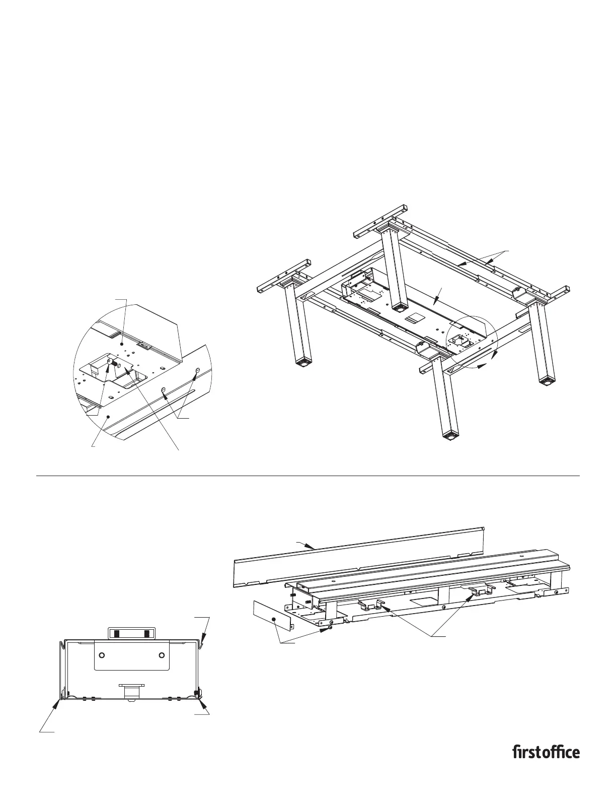
1. Adjust the benching frame assembly to have a distance
between cross bars slightly larger than the width of the
cable carrier. Leave one end of the spanner bars loose
for final adjustment.
2. Attach the cable carrier to the cross bars using (4) M8x20
bolts through the inside of the cable carrier mounting
L-bracket and into the insert nuts in the side of the benching
cross bars.
3. Once the cable carrier is secured to the benching cross bars
tighten the remaining spanner bar set screws.
INSTRUCTION SHEET # 2575INS
PART #1730532
A
SPANNER BARS
CABLE CARRIER
NOTE: ILLUSTRATION SHOWN
FROM UNDERNEATH
DETAIL A
SCALE 1 : 4
(4) M8x20
MACHINE SCREW
CROSS BAR INSERT NUT
MOUNTING L BRACKET
BENCHING CROSS BAR
CABLE CARRIER ASSEMBLY
A
LOWER SPRING CLIP
UPPER HANGING LEDGE
TO REMOVE PULL OUTWARD AT BOTTOM EDGE
TO RELEASE THE SPRING CLIP AND LIFT UPWARD
TO REMOVE FROM THE HANGING LEDGE
REMOVING THE ACCESS PANELS
PRE-ASSEMBLED ELECTRICAL
BRACKETS TO ATTACH POWER BLOCK
REMOVABLE ACCESS
PANEL BOTH SIDES
END CAP SLIDES INTO END
OF CABLE CARRIER & ATTACHES
WITH (2) M6X8 MACHINE SCREWS