General operation
Seite/Page 24 - Kaptitel/Chapter 2: General operation 10.5.17
2.7.6 Configuration and adjustment
2.7.6.1 Configuration and setting sheet KE05
Standard jumpering for use as Slave-Panel in connection with two Master-Slave-Adapters RE0706 and a Generator
Control Panel P6+ RE0703 as Master-Panel. Panel only for 12 V-operation.
The safety device is installed with the value 0,63 AT. The circuit parts for 24 V-operation are not equipped.
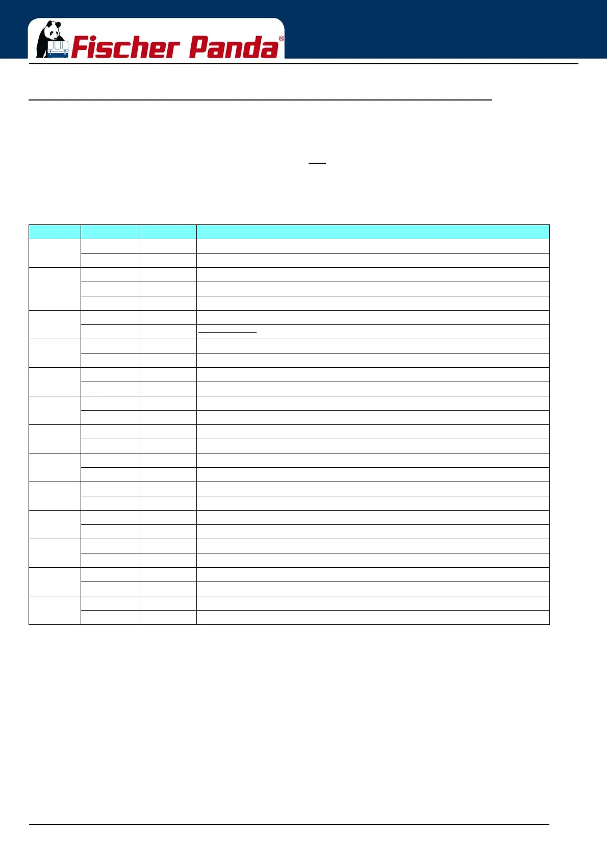
Fig. 2.7.6-1: Settings of soldered jumper for this configuration (column Conf.)
The solder jumpers are marked on the printed circuit board (with jumper no. and at three-part solder jumper with soldering surface no.)
X = Jumper must be so set
XM = Jumper, function must be so set on the master panel is selected
M = Jumper must be set exactly the same, as on the master panel,
(1): Equivalent resistance for load control lamp e.g. for use with three-phase alternator also integrated automatic controller of Bosch. The resistance value is 68 Ω 3W,
i.e. only for 12 V.
(2): A closed contact switches the appropriate input to GND.
Jumper Status Conf. Description
J1 closed during operation of the start button heat is along-operated
open XM Function deactivated
J3 1-2 Dynamo excitation resistor 68R is switched on with Fuel-Pump (1)
2-3 Dynamo excitation resistor 68R is switched on with Panel-ON (1)
open XM Dynamo excitation resistor is deactivated
J101 closed M 12 V - operation
open M 24 V - operation
(not possible)
J201 1-2 T-Engine-input, for contact, which opens in case of error (2)
2-3 XM T-Engine-input, for contact, which closes in case of error (2)
J202 1-2 Water leak-input / Replace air filter, for contact, which opens in case of error (2)
2-3 XM Water leak-input / Replace air filter, for contact, which closes in case of error (2)
J203 1-2 Oil-Press-input, for contact, which opens in case of error (2)
2-3 XM Oil-Press-input, for contact, which closes in case of error (2)
J204 1-2 AC-Fault-input / Fuel level, for contact, which opens in case of error (2)
2-3 XM AC-Fault-input / Fuel level, for contact, which closes in case of error (2)
J205 1-2 T-Winding-input, for contact, which opens in case of error (2)
2-3 XM T-Winding-input, for contact, which closes in case of error (2)
J206 1-2 M Input Water leak has red LED and switches off
2-3 M Input Water leak has yellow LED and does not switch off
J207 1-2 M Input AC-Fault has red LED and switches off
2-3 M Input AC-Fault has yellow LED and does not switch off
J208 1-2 M DC-Control-Signal (-) = OK dynamo 12 V at Kubota Z 482 / D 722 engines
2-3 M DC-Control-Signal (+) = OK three-phase DC-alternator
J209 1-2 M DC-Control-Signal (-) = OK dynamo 12 V at Kubota Z 482 / D 722 engines
2-3 M DC-Control-Signal (+) = OK three-phase DC-alternator
J210 closed Input AC-Fault has Pull-Up-current
10 mA
open XM Input AC-Fault has Pull-Up-current
2,5 mA