Do you have a question about the Fisher & Paykel DE50F56A2 and is the answer not in the manual?
Lists electrical ratings, power consumption, and current requirements.
Details the types, power, and specifications of the motor.
Information on the specifications of the heating element.
Details thermostat operating temperatures and current rating.
Resistance values for the exhaust sensor at different temperatures.
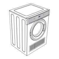
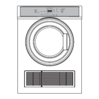
Explains the airflow path and operational mechanics of a vented dryer.
Describes the drum drive system, motor, and mounting components.
Explains the function of temperature sensors and thermostats.
Details the two thermostats and their trip/reset temperature points.
Locates the exhaust sensor and describes its function.
Procedures for testing the motor at the control panel and directly at the motor.
Instructions for testing motor resistance via control panel terminals.
Instructions for testing motor resistance directly at the motor terminals.
Procedures for testing NTC, door switch, heater, and thermostat at the control panel.
Tests the resistance of the NTC sensor located in the exhaust duct.
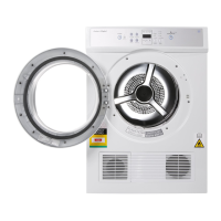
Tests the door switch resistance on the DE50F56EW model.
Tests the door switch resistance on DE40F56A and DE50F56A models.
Tests the door switch resistance on DE40F56A2 and DE50F56A2 models.
Tests the heater and thermostat circuit for the DE50F56EW model.
Tests the heater and thermostat circuit for DE40F56AW and DE50F56AW models.
Tests the heater and thermostat circuit for DE40F56A2 and DE50F56A2 models.
Tests the functionality of the exhaust sensor and door switch.
Explains how fault codes are displayed and interpreted on the panel.
Details fault code 0101 for a faulty exhaust sensor.
Details fault code 1010 for exhaust sensor shorted to cabinet.
Details fault code 0110 for faulty exhaust or ambient sensor.
Details fault code 1101 for an over-temperature condition.
Details fault code 1111 for brown out conditions.
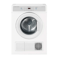
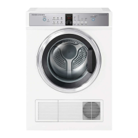
| Capacity | 5 kg |
|---|---|
| Energy Rating | 2 Stars |
| Control Type | Electronic |
| Width | 600 mm |
| Height | 850 mm |
| Delay Start | Yes |
| Child Lock | Yes |
| Type | Vented |