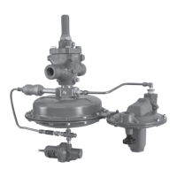
Type 1290
11
and diaphragm plate (key 8). To separate the stem
(key 12) from the diaphragm plate, remove the stem
cap screw (key 9).
4. To remove the case O-ring (key 5), unscrew the
four case cap screws (key 4), remove the upper
diaphragm case (key 2) and remove the case O-ring.
To remove the stem O-rings, bearings and wiper
ring (keys 6, 56 and 57, respectively), remove the
loading and control lines. Unscrew the bonnet
(key 3) and remove the O-rings.
5. Lubricate both stem O-rings (key 6) and wiper ring
(key 57), and install them with the stem bearings
(key 56) in bonnet (key 3). Lubricate the case O-ring
(key 5), and install it in the bonnet. Line up the holes
in the upper diaphragm casing (key 2) and the
bonnet; insert and tighten the four case cap screws
(key 4) to 24 to 30 ft-lbs / 33 to 41 N•m of torque.
Thread the bonnet into the main valve body (key 1,
Figure 6).
6. Secure the diaphragm plate (key 8) to the stem
(key 12) with the stem cap screw (key 9). Lay the
diaphragm (key 7), diaphragm plate and stem
assembly into the lower diaphragm case (key 2)
so the diaphragm convolution laps up over the
diaphragm plate according to Figure 7. Install the
stem slowly up into the bonnet (key 3) to prevent
stem or O-ring damage, and secure the lower
diaphragm case to the upper diaphragm case
(key 1) with the cap screws and nuts. Tighten the
cap screws (key 4) and nuts using a criss-cross
pattern with 24 to 30 ft-lbs / 33 to 41 N•m
of torque.
7. Grease the stem O-rings (key 6) through the
grease tting (key 28) until excess grease starts
coming out the vent assembly (key 27). Install the
pipe nipple and line tubing if they were removed
during maintenance.
Parts Ordering
Each Type 1290 vapor recovery regulator is assigned
a serial number which can be found on the nameplate
on the main valve actuator. Refer to this number when
contacting your local Sales Ofce for assistance, or
when ordering replacement parts. When ordering a
replacement part, be sure to reference the key number
of each needed part and include the complete
11-character part number from the following parts list.
Separate kits containing all recommended spare parts
are available for both the main valve and pilot.
Parts marked NACE can be used for sour gas service
as detailed in the NACE International standard MR0175.
Parts referenced in the parts list can be found in Figures 6
through 10.
Parts List
Type EGR Main Valve (Figure 6)
Key Description Part Number
Parts Kit, Nitrile (NBR) Elastomers (Included are
keys 4, 7, 12, 15, 17, 21, 36 and 37)
NPS 1 / DN 25 R63EGX00112
NPS 2 / DN 50 R63EGX00122
NPS 3 / DN 80 R63EGX00132
NPS 4 / DN 100 R63EGX00142
NPS 6, 8 x 6 and 12 x 6 /
DN 150, 200 x 150 and 300 x 150 R63EGX00162
1 Body See Table 3
2 Body Flange
Cast iron, ENC
NPS 2 / DN 50 25A3168X012
NPS 3 / DN 80 24A9034X012
NPS 4 / DN 100 25A2309X012
NPS 6, 8 x 6 and 12 x 6 /
DN 150, 200 x 150 and 300 x 150 34A8172X012
WCC Steel, ENC, Heat-treated
NPS 1 / DN 25 24A6779X012
NPS 2 / DN 50 25A2254X012
NPS 3 / DN 80 25A2300X012
NPS 4 / DN 100 24A9032X012
NPS 6, 8 x 6 and 12 x 6 /
DN 150, 200 x 150 and 300 x 150 34A7152X012
CF8M Stainless steel, ENC (NACE)
NPS 1 / DN 25 24A6779X062
NPS 2 / DN 50 25A2254X082
NPS 3 / DN 80 25A2300X122
NPS 4 / DN 100 24A9032X042
NPS 6, 8 x 6 and 12 x 6 /
DN 150, 200 x 150 and 300 x 150 34A7152X052
3 Cap Screw, Zinc-plated steel
(cast iron and steel bodies)
NPS 1 / DN 25 (4 required) 1R281124052
NPS 2 / DN 50 (8 required) 1A453324052
NPS 3 / DN 80 (8 required) 1A454124052
NPS 4 / DN 100 (8 required) 1A485724052
NPS 6, 8 x 6 and 12 x 6 /
DN 150, 200 x 150 and 300 x 150 (12 required) 1U513124052
3 Stud Bolt, Stainless steel,
(Stainless steel body, not shown)
NPS 1 / DN 25 (4 required) 1R284835222
NPS 2 / DN 50 (8 required) 1K242935222
NPS 3 / DN 80 (8 required) 1A378135222
NPS 4 / DN 100 (8 required) 1R369035222
NPS 6, 8 x 6 and 12 x 6 /
DN 150, 200 x 150 and 300 x 150 (12 required) 1A365635222
4* Gasket, Composition
NPS 1 / DN 25 14A6785X012
NPS 2 / DN 50 14A5685X012
NPS 3 / DN 80 14A5665X012
NPS 4 / DN 100 14A5650X012
NPS 6, 8 x 6 and 12 x 6 /
DN 150, 200 x 150 and 300 x 150 14A6984X012
*Recommended spare part.

 Loading...