Type 1290
2
Specications
This section lists the specications for the Type 1290 vapor recovery regulator. Specications for a given regulator as it
originally comes from the factory are stamped on the regulator nameplate located on the actuator, while the pilot control
spring range appears on the pilot spring case nameplate.
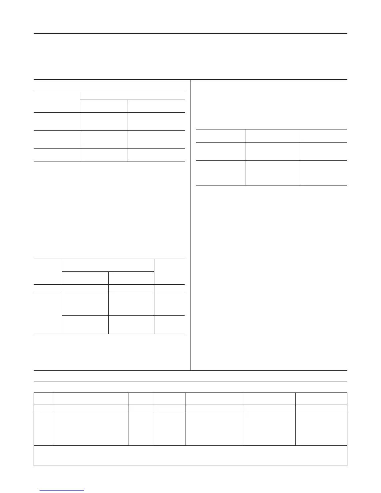
Body Sizes and End Connection Styles
(1)
Maximum Inlet Pressure
(2)
Type T208P Pilot Constructions: 20 psig / 1.4 bar
Type EGR Main Valve: See Table 2
For Fluorinated Ethylene Propylene (FEP)
Diaphragm: 10 psig / 0.69 bar
Maximum Differential Pressure
(2)
35 psi / 2.4 bar
Control Pressure Ranges (Type T208P or
T208PL Pilot)
(2)
See Table 1
Type MR95H Supply Pressure Settings
PILOT
TYPE
TYPE EGR MAIN VALVE WITH
GREEN SPRING, NPS / DN
SPRING
COLOR
1, 2, 3 or 4 /
25, 50, 80 or 100
6 or 8 x 6 /
150 or 200 x 150
T208PL 8 psig / 0.55 bar 13 psig / 0.90 bar Black
T208P
8 psig / 0.55 bar
8 psig / 0.55 bar
9 psig / 0.62 bar
10 psig / 0.69 bar
13 psig / 0.90 bar
13 psig / 0.90 bar
14 psig / 0.97 bar
14 psig / 0.97 bar
Orange
Red
Olive Green
Yellow
11 psig / 0.76 bar
14 psig / 0.97 bar
15 psig / 1.0 bar
15 psig / 1.0 bar
18 psig / 1.2 bar
20 psig / 1.4 bar
Light green
Light Blue
Black
Type T208P or T208PL Pilot Orice Diameter
3/8 in. / 9.5 mm
Control Line Connection
1/2 NPT
1. End connections for other than U.S. standards can usually be provided. Consult your local Sales Ofce.
2. Pressure/temperature limits in this Instruction Manual and any applicable standard or code limitation should not be exceeded.
BODY SIZE,
NPS / DN
TYPE EGR MAIN VALVE END CONNECTION STYLE
Cast Iron
WCC Steel or
CF8M Stainless steel
1 or 2 /
25 or 50
NPT, CL125 FF or
CL250 RF anged
NPT, SWE, BWE, CL150 RF,
CL300 RF, CL600 RF or
PN 16/25/40 anged
3, 4 or 6 /
80, 100 or 150
CL125 FF or
CL250 RF anged
BWE, CL150 RF,
CL300 RF, CL600 RF or
PN 16 anged
8 x 6 or 12 x 6 /
200 x 150 or 300 x 150
- - - -
BWE, CL150 RF, CL300 RF,
CL600 RF or PN 25 anged
Exhaust Line Connection
3/4 NPT
Supply Pressure and Spring Case Connections
1/4 NPT
Port Diameters and Travels
BODY SIZE,
NPS / DN
PORT DIAMETER,
In. / mm
TRAVEL,
In. / mm
1 / 25
2 / 50
3 / 80
1-5/16 / 33
2-3/8 / 60
3-3/8 / 86
3/4 / 19
1-1/8 / 29
1-1/2 / 38
4 / 100
6 / 150
8 x 6 / 200 x 150
12 x 6 / 300 x 150
4-3/8 / 111
7-3/16 / 183
7-3/16 / 183
7-3/16 / 183
2 / 51
2 / 51
2 / 51
2 / 51
Main Valve Temperature Capabilities
(2)
Nitrile (NBR):
-20 to 180°F / -29 to 82°C
Fluorocarbon (FKM):
For In. w.c. Setpoints:
40 to 300°F / 4 to 149°C
For psig Setpoints:
0 to 300°F / -18 to 149°C
Ethylenepropylene (EPDM):
-20 to 275°F / -29 to 135°C
Peruoroelastomer (FFKM):
-20 to 300°F / -29 to 149°C
Pilot Temperature Capabilities
See Table 4
Approximate Weights:
NPS 1 / DN 25: 85 lbs / 39 kg
NPS 2 / DN 50: 100 lbs / 45 kg
NPS 3 / DN 80: 145 lbs / 66 kg
NPS 4 / DN 100: 195 lbs / 88 kg
NPS 6 / DN 150: 380 lbs / 172 kg
NPS 8 x 6 / DN 200 x 150: 740 lbs / 336 kg
NPS 12 x 6 / DN 300 x 150: 1265 lbs / 574 kg
Table 1. Control Pressure Ranges
PILOT
TYPE
CONTROL PRESSURE RANGE
(1)
SPRING
COLOR
SPRING PART
NUMBER
BUILDUP TO WIDE-OPEN
(TYPE EGR MAIN VALVE)
SPRING WIRE DIAMETER,
In. / mm
SPRING FREE
LENGTH, In. / mm
T208PL 0.5 to 1.5 in. w.c. / 1 to 4 mbar
(2)
Black 1B413627222 0.25 in. w.c. / 0.60 mbar 0.075 / 1.90 2.25 / 57.2
T208P
1 to 2.5 in. w.c. / 2 to 6 mbar
(2)(3)
2 to 7 in. w.c. / 5 to 17 mbar
(2)(4)
5 to 16 in. w.c. / 12 to 40 mbar
0.5 to 1.2 psig / 35 to 83 mbar
1.0 to 2.5 psig / 0.07 to 0.17 bar
2.5 to 4.5 psig / 0.17 to 0.31 bar
4.5 to 7 psig / 0.31 to 0.48 bar
Orange
Red
Olive Green
Yellow
Light Green
Light blue
Black
1B558527052
1B653827052
1B653927022
1B537027052
1B537127022
1B537227022
1B537327052
0.25 in. w.c. / 0.60 mbar
0.25 in. w.c. / 0.60 mbar
0.25 in. w.c. / 0.60 mbar
0.05 psig / 3.40 mbar
0.10 psig / 6.90 mbar
0.15 psig / 10.0 mbar
0.20 psig / 14.0 mbar
0.072 / 1.83
0.085 / 2.16
0.105 / 2.67
0.114 / 2.90
0.156 / 3.96
0.187 / 4.75
0.218 / 5.54
3.25 / 83
3.62 / 92.0
3.75 / 95.2
4.31 / 109
4.06 / 103
3.94 / 100
3.98 / 101
1. Spring ranges based on pilot being installed with the spring case pointed down.
2. Do not use Fluorocarbon (FKM) diaphragm with this spring at diaphragm temperatures lower than 60°F / 16°C.
3. When using a Fluorocarbon (FKM) diaphragm, the minimum outlet pressure is 2 in. w.c. / 5 mbar.
4. When using a Fluorocarbon (FKM) diaphragm, the minimum outlet pressure is 2.5 in. w.c. / 6 mbar.