133 Series
4
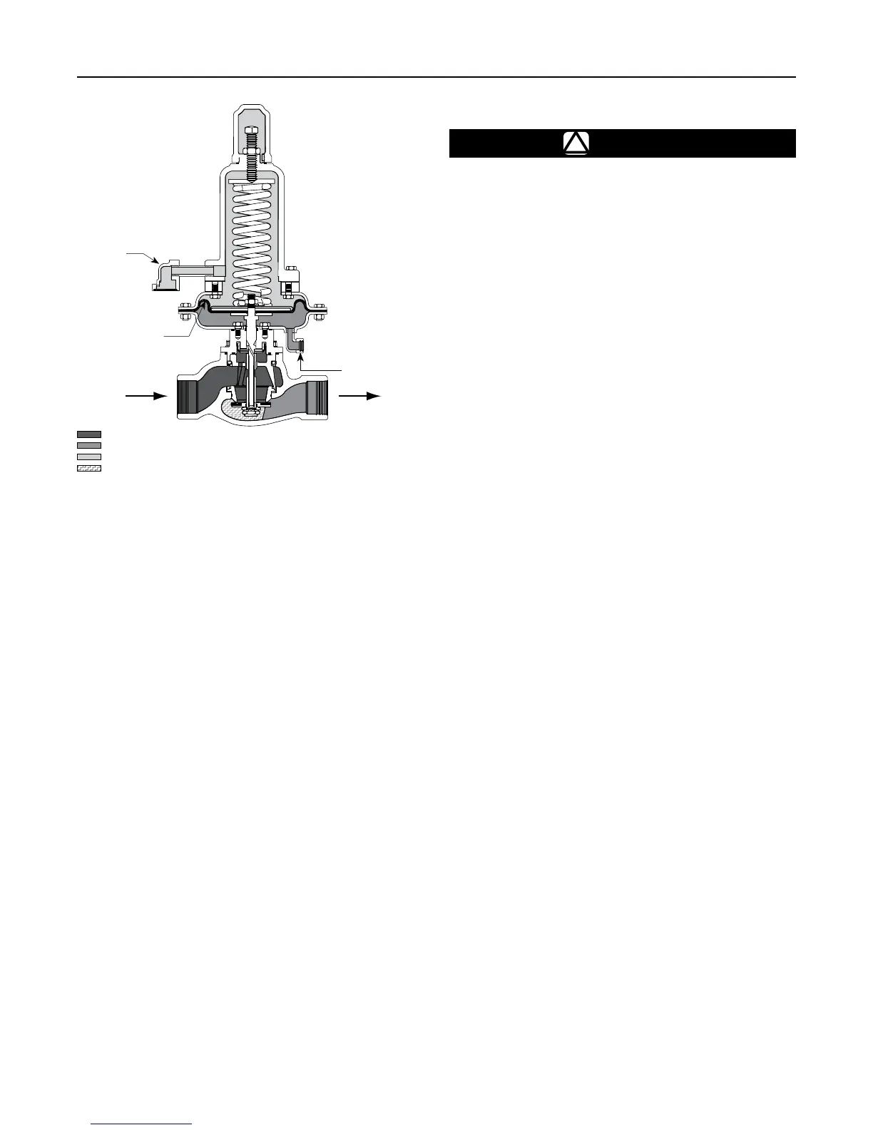
Figure 3. Operational Schematic of Type 133HP
If the regulator has threaded end connections, coat
external threads with pipe compound. For anged
end connections, tighten the ange bolts evenly.
Install a three valve bypass around the 133 Series if
continuous operation is necessary.
The regulator must be protected from damage by
vehicles and other outside sources.
Overpressure Protection
The 133 Series regulators have an outlet pressure
rating that is lower than the inlet pressure rating. Some
type of overpressure protection is needed if the actual
inlet pressure exceeds the outlet pressure rating.
Maximum operating inlet pressure for the 133 Series
regulators is given in Table 2. All models must
be protected against inlet pressure above their
listed maximum.
Regulator operation below these emergency pressure
limitations does not preclude the possibility of damage
from external sources or from debris in the gas line.
The regulator should be inspected for damage after any
overpressure condition.
Downstream Control Line
!
WARNING
Downstream control line is Srequired for
proper operation of these regulators.
An external downstream control line must be installed
before putting the 133 Series regulators in operation.
Without the control line, the regulator will remain wide-
open. The downstream control line should be a pipe
of at least 1/2 in. / 12.7 mm diameter; connect it to the
downstream pipe line at least 5 to 10 pipe diameters
from the regulator and in a straight section of pipe.
The external downstream control line connection on
the Type 133HP is 1/4 NPT.
Vent
The 133 Series vent is screened to prevent insects
or foreign material from entering. The Types 133H,
133L and 133Z regulators have a 1 NPT (internal)
connection and the Type 133HP has a 1/2 NPT
internal connection. If a vent to the atmosphere is
required for indoor installations, do the following:
• For Types 133H, 133L and 133Z — remove the
snap ring and screen (keys 8J and 8H, Figure 10,
11 or 12) and pipe the vent to the outside.
• For Type 133HP — remove the Type Y602-7
screened vent assembly and pipe nipple (keys 50
and 49, Figure 14) from the spring case (key 8)
and pipe the vent to the outside.
The vent pipe should be as short as possible with
minimum number of bends or elbows. The pipe should
also have the largest practical diameter. Install a
weather and bug resistant vent assembly on the outside
end of the vent pipe.
For indoor installation that have been piped to the
outside and for outdoor installations, the vent opening
must be positioned so that water, ice and other foreign
material cannot enter the spring case. Use care not to
place the vent opening below downspouts and eaves.
The vent opening should be checked periodically to be
sure that the opening has not been plugged with foreign
material. On some installations it may be necessary to
provide additional protection from the elements.
Type 133HP
A6883
June 2009
Type 133HP
INLET PRESSURE
OUTLET PRESSURE
ATMOSPHERIC PRESSURE
BOOST PRESSURE
INLET PRESSURE
OUTLET PRESSURE
ATMOSPHERIC PRESSURE
INTERMEDIATE PRESSURE
PILOT SUPPLY PRESSURE
VACUUM PRESSURE
TANK PRESSURE
VAPOR PRESSURE
LOADING PRESSURE
RELIEF PRESSURE
BOOST PRESSURE
A6883
INLET PRESSURE
OUTLET PRESSURE
ATMOSPHERIC PRESSURE
BOOST PRESSURE
VENT
ASSEMBLY
DIAPHRAGM
DOWNSTREAM
CONTROL LINE