133 Series
5
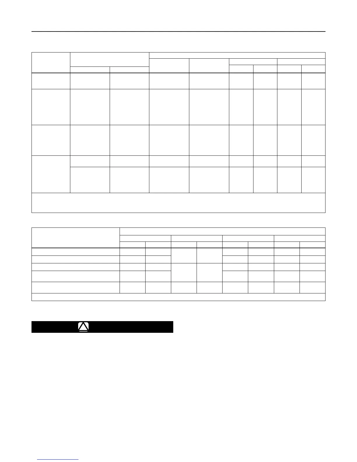
Table 1. 133 Series Outlet Pressure Ranges, Control Springs
Table 2. Maximum Inlet and Outlet Pressures
TYPE
OUTLET PRESSURE RANGE
CONTROL SPRINGS
Part Number Color Code
Free Length Wire Diameter
In. mm In. mm
psig bar
133H
(1)
1.5 to 3
2 to 5
5 to 10
0.10 to 0.21
0.14 to 0.34
0.34 to 0.69
1H975927032
10A9440X012
1J146927142
Orange
Yellow
Blue
6.91
6.47
6.19
176
164
157
0.250
0.283
0.375
6.35
7.19
9.52
133HP
(1)
2 to 5
4.5 to 10
6 to 20
16 to 30
26 to 40
36 to 50
45 to 60
0.14 to 0.34
0.31 to 0.69
0.41 to 1.4
1.1 to 2.1
1.8 to 2.8
2.5 to 3.4
3.1 to 4.1
17B8632X012
17B8633X012
10C1238X012
10C1240X012
10C1241X012
10C1242X012
10C1243X012
Yellow
Orange
Silver
Red
Blue
Green
White
8.50
8.50
8.25
8.25
8.25
8.25
8.25
216
216
210
210
210
210
210
0.282
0.343
0.375
0.438
0.500
0.500
0.531
7.16
8.71
9.53
11.1
12.7
12.7
13.5
133L
(1)
and 133H
(2)
2 to 4 in. w.c.
3.5 to 6 in. w.c.
5 to 9 in. w.c.
8.5 to 18 in. w.c.
14 to 28 in. w.c.
0.75 to 2
5 to 10 mbar
9 to 15 mbar
12 to 22 mbar
21 to 45 mbar
35 to 70 mbar
0.05 to 0.14
1D892527022
1D892627022
1D892727012
1D893227032
1D893327032
1H975827032
Brown
Red
Black
White
Green
Blue
6.13
7.53
7.88
7.50
7.25
7.09
156
191
200
190
184
180
0.109
0.112
0.130
0.156
0.182
0.225
2.77
2.85
3.30
3.96
4.62
5.72
133Z
(1)
-1 to 1 in. w.c. -3 to 3 mbar
1K633427012
(Extension Spring)
Unpainted 2.00 50.8 0.075 1.91
0 to 4 in. w.c. 0 to 10 mbar
1K633427012
(Extension Spring)
and
1D892527022
(Compression Spring)
Unpainted
Brown
2.00
6.13
50.8
156
0.075
0.109
1.91
2.77
1. Pressure ranges shown are correct if the regulator is installed with the actuator portion above the body portion. If the regulator is installed with the actuator portion below the body, the
pressure ranges will be lowered by approximately 2 in. w.c. / 5 mbar for the Type 133L and by approximately 3 in. w.c. / 7 mbar for the Types 133H and 133Z.
2. If the 2 in. w.c. / 5 mbar to 2 psig / 0.14 bar springs (all 6 ranges) are used in the Type 133H, the pressure ranges will increase by approximately 1 in. w.c. / 2 mbar due to the weight of
the Type 133H parts (assuming that the actuator is installed above the body).
PRESSURES
TYPE NUMBER
133H 133HP 133L 133Z
psig bar psig bar psig bar psig bar
Maximum Operating Inlet Pressure 60 4.1
150 10.5
60 4.1 20 1.4
Maximum Emergency Inlet Pressure 125 8.6 125 8.6 125 8.6
Maximum Operating Outlet Pressure
(1)
10 0.69
Setpoint
plus 40
Setpoint
plus 2.8
2 0.14 4 in. w.c. 10 mbar
Maximum Outlet Pressure Over
Outlet Pressure Setting
3 0.21 3 0.21 3 0.21
Maximum Emergency Outlet
(Casing) Pressure
15 1.0 150 10.5 15 1.0 15 1.0
1. With highest spring range available only.
Startup
!
WARNING
If the downstream system is already
pressured by another regulator or by a
manual bypass, then extra precautions
must be taken when placing the 133 Series
in service. The outlet of the regulator must
never be subjected to pressure higher
than the inlet pressure or the balancing
diaphragm may be damaged. Also, the
control line pressure must never exceed
the set point dictated by the spring setting
by more than 3 psig / 0.21 bar or the
valve seat or diaphragm plates can be
damaged. The procedure used in putting
the regulator in service must be planned
accordingly. Pressure gauges should
always be used to monitor downstream
and control line pressures during startup.
If the downstream system is not pressured by
another regulator or by manual bypass, use the
following procedure:
1. Check to see that all appliances are turned off.
2. Slowly open the upstream shutoff valve.
3. Slowly open the downstream shutoff valve.
4. Check all connections for leaks.
5. Make nal control spring adjustments according to
the adjustment procedures.
 Loading...


