133 Series
7
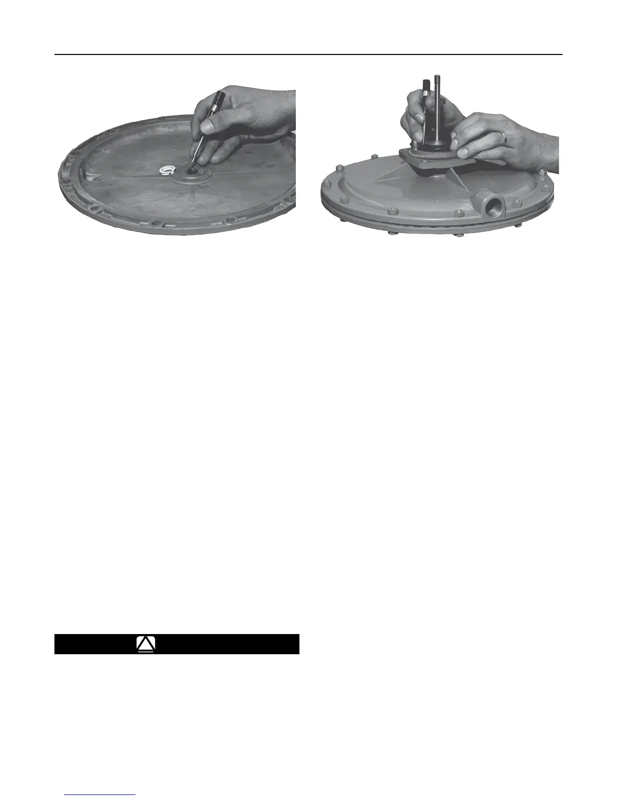
W1372/IL
Figure 5. Inspecting Guide Bushing and Stem Seal O-ring
W1371/IL
Figure 6. Installing Balancing Diaphragm. The Side of
Diaphragm Marked Piston Side Must Face Casing.
4. Insert a 1/2 in. / 13 mm open-end wrench between
the legs of the cage (key 5) and place the wrench
on the stem sleeve wrench ats. Hold this wrench
while unscrewing the nut (key 31) to prevent stem
and stem sleeve (keys 18 and 25) rotation and
diaphragm (key 15) and balancing diaphragm
(key 22) damage due to twisting (see Figure 4).
5. Remove the washer, registration disk and valve disk
(keys 30, 29 and 28). To remove the restriction collar
(key 46, Figure 13) (if used), loosen the set screw
(key 47, Figure 13) and slip the E-ring (key 26,
Figure 13) and collar off of the stem (key 18).
Remove the orice (key 2) by rotating it until the
pins (key 5A) in the cage line up with the slots in
the orice; then, lift off the orice. Replace the valve
disk and orice if necessary.
6. Loosen the set screws (key 39) in the cage (key 5)
and remove the roll pin (key 27) from the stem
(key 18). Remove the cage and stem sleeve
(key 25), the sealing washer (key 17) under
the balancing diaphragm (key 22), at washers
(key 23), balancing diaphragm and balancing
diaphragm plate (key 21). Replace sealing washer
and balancing diaphragm if necessary.
!
WARNING
To avoid personal injury due to the
sudden uncontrolled movement of parts,
do not loosen the diaphragm casing
cap screws (keys 35 and 36) when the
control spring (key 12) has spring force
applied to it.
Release the spring compression as
described in step 7.
7. To inspect or replace the upper stem seal O-ring
(key 19) or main diaphragm (key 15) on the
Type 133L or 133H (Figure 10 or 11), remove the
closing cap (key 9) and inspect the closing cap
gasket (key 10). Release spring compression
by slowly turning the adjusting screw (key 11)
counterclockwise and remove the spring (key 12).
For Type 133Z (Figure 12), remove the closing cap
(key 9) and inspect the closing cap gasket (key 10).
Release any spring compression by slowly turning
the adjusting screw (key 11) counterclockwise. Lift
the adjusting screw assembly (keys 11, 41, 42, 43
and 45) out of the spring case with pliers. Unhook
the extension spring (key 44) from the spring
retainer (key 42). Remove the compression spring
(key 12) if one is used.
8. Unscrew the cap screws and nuts (keys 35 and 36)
and remove the spring case (key 8A).
9. Pull out the diaphragm and stem as assembly;
replace diaphragm (key 15) and sealing washer
(key 17) if necessary. When removing or replacing
the diaphragm, clamp the smallest diameter portion
of the stem in a vise while turning the nut (key 20).
10. If necessary, replace the bearing (key 6) and the
upper stem seal O-ring (key 19, Figure 5). Before
reassembling, coat the O-ring with O-ring sealant
and lubricant.