Instruction Manual
D200099X012
249 Caged Sensors
April 2017
16
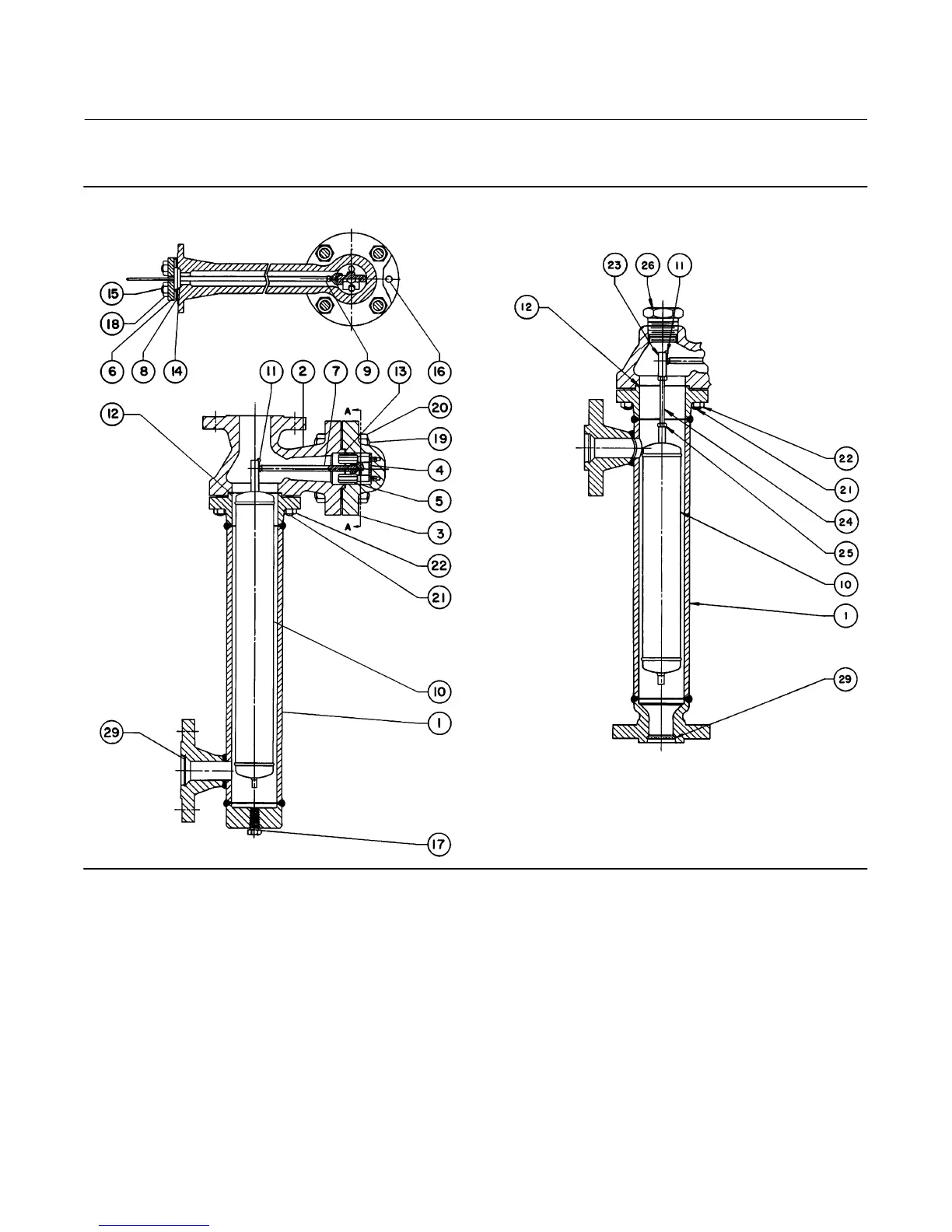
Figure 10. Fisher 249C Sensor Construction
30A7425‐B
30A7428‐B
DETAIL OF STYLE 3 OR 4 CONNECTIONS
SECTION A‐A
Key Description
17 Pipe Plug
(1)
For 249B, styles 2, 3, steel
For 249C, styles 2, 3, S31600
For 249K and 249L styles 2, 3, steel
18 Hex Nut
(1)
(4 req'd)
For 249 and 249B, steel‐B7
249C, steel‐B7
For 249K and 249L steel B7
19 Cap Screw
(1)
, steel B7 (4 req'd)
For 249
CL125
CL250
Key Description
19 Bolt Stud
(1)
, steel B7 (4 req'd)
For 249B, 249C
For 249K
20 Hex Nut
(1)
, steel
For 249
CL125 (12 req'd)
CL250 (4 req'd)
For 249B, 249C (8 req'd)
For 249K (8 req'd)
For 249L (4 req'd)
1. This part is available in a wide variety of materials of construction, part
dimensions, or other specifications. Listed here are standard or typical materials,
dimensions, or specifications. Contact your Emerson sales office for assistance in selecti
of specific materials, dimensions, or specifications.