Instruction Manual
D200099X012
249 Caged Sensors
April 2017
17
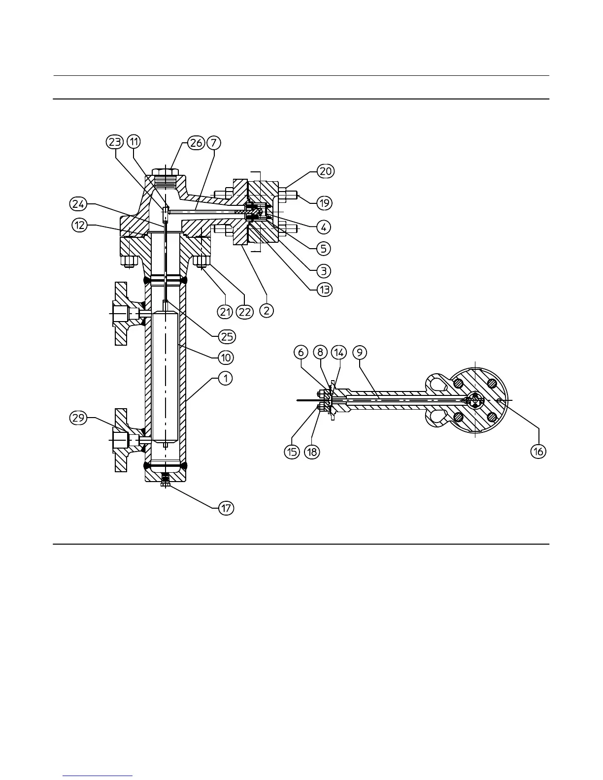
Figure 11. Fisher 249K Sensor Construction
30A7429‐D
SECTION A‐A
A
A
Key Description
21 Cap Screw
(1)
, steel B7 (8 req'd)
For 249
CL125
CL250
21 Bolt Stud
(1)
, B7 (8 req'd)
For 249B
For 249C
For 249K
For 249L
Key Description
22 Hex Nut
(1)
, steel
For 249
CL250 (8 req'd)
For 249B (16 req'd)
For 249C (8 req'd)
For 249K (8 req'd)
For 249L (16 req'd)
23 Displacer Stem End Piece
(1)
, S31600
1. This part is available in a wide variety of materials of construction, part dimensions, or other
specifications. Listed here are standard or typical materials, dimensions, or specifications.
Contact your Emerson sales office for assistance in selection of specific materials, dimensions,
or specifications.