Instruction Manual
D100307X012
657 Size 80 and 100 Actuators
December 2010
2
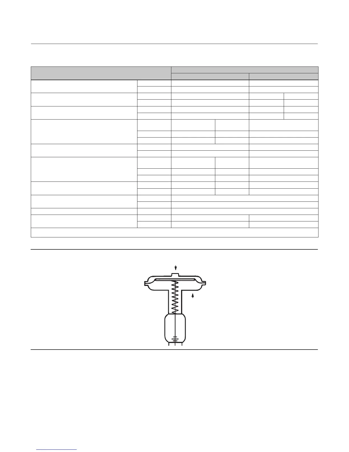
Table 1. Specifications
SPECIFICATIONS
ACTUATOR SIZE
80 100
Nominal Effective Diaphragm Area
cm
2
1761 2902
inch
2
273 450
Yoke Boss Diameters
mm 127 127 178
inch 5 5H
(1)
7
Acceptable Valve Stem Diameters
mm 25.4 or 31.8 31.8 50.8
inch 1 or 1‐1/4 1‐1/4 2
Maximum Allowable Output Thrust
Standard Cast Iron
Construction
All Steel
Construction
N 62942 88075 200170
lb 14150 19800 45000
Maximum Travel
mm 76 102
inch 3 4
Maximum Casing Pressure for Actuator Sizing
Standard Cast Iron
Construction
All Steel
Construction
bar 3.4 4.9 6.9
psig 50 70 100
Maximum Diaphragm Casing Pressure
(2)
bar 4.1 5.5 7.9
psig 60 80 115
Material Temperature Capabilities
_C -40 to 82
_F -40 to 180
Pressure Connections 1/4 NPT internal
Approximate Weights Without Handwheel
kg 234 346
lb 515 762
1. Heavy actuator‐to‐bonnet bolting.
2. This maximum casing pressure is not to be used for normal operating pressure.
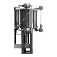
Figure 2. Schematic Representation of Fisher 657 Actuator
SPRING LIFTS
AIR PUSHES STEM DOWN
AF3833‐A
A0792‐2
Description
The 657 actuator (figure 1) is a direct‐acting, spring‐opposed diaphragm actuator used for automatic operation of
control valves. The actuator positions the valve plug in response to varying pneumatic loading pressure on the
diaphragm. Figure 2 shows the operation of these actuators.
A 657 actuator can be furnished with either a top‐mounted or side‐mounted (size 80 only) handwheel assembly. A
top‐mounted handwheel assembly is normally used as an adjustable‐up travel stop. The size 100 top‐mounted