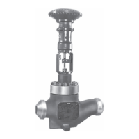
EH Valves (NPS 8 through 14)
Instruction Manual
April 2009
3
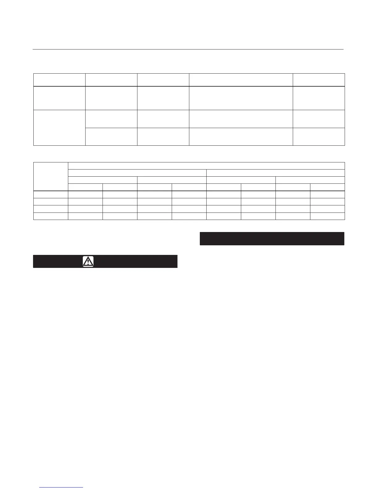
Table 3. Additional Shutoff Classification
VALVE DESIGN
(PRESSURE RATING)
VALVE SIZE, NPS
PORT DIAMETER,
INCHES
CAGE STYLE
ANSI/FCI LEAKAGE
CLASS
EHD
(CL500)
8
10
7
Equal Percentage
Modified Equal Percentage
Linear (std. cage)
Linear (Whisper III, A1, B3, C3)
V with
optional Bore seal trim
EHD
(CL2500)
8
10
5.375
Equal Percentage, Modified Equal Percentage,
Linear (std. cage),
Linear (Whisper III, A1, B3, C3, D3)
V with
optional Bore seal trim)
12
14
7
Equal Percentage, Modified Equal Percentage,
Linear (std. cage),
Linear (Whisper III, A1, B3, C3, D3)
V with
optional Bore seal trim)
Table 4. Approximate Weights (Valve Body and Bonnet Assemblies)
VALVE
SIZE,
NPS
WEIGHTS
CL1500 CL2500
Buttwelding Ends Flanged Buttwelding Ends Flanged
Kilograms Pounds Kilograms Pounds Kilograms Pounds Kilograms Pounds
8 1400 3100 1700 3700 1900 4100 2200 4700
10 1500 3300 1900 4100 2000 4400 - - - - - -
12 3400 7300 3900 8600 3400 7600 - - - - - -
14 3400 7300 - - - - - - 3400 7600 - - - - - -
Installation
WARNING
Always wear protective gloves,
clothing, and eyewear when
performing any installation operations
to avoid personal injury.
To avoid personal injury or property
damage resulting from the sudden
release of pressure, do not install the
valve assembly where service
conditions could exceed the limits
given in this manual or on the
appropriate nameplates. Use
pressure-relieving devices as required
by government or accepted industry
codes and good engineering practices.
Check with your process or safety
engineer for any additional measures
that must be taken to protect against
process media.
If installing into an existing
application, also refer to the WARNING
at the beginning of the Maintenance
section in this instruction manual.
CAUTION
The valve configuration and
construction materials were selected
to meet particular pressure,
temperature, pressure drop, and
controlled fluid conditions. Because
some body/trim material combinations
are limited in their pressure drop and
temperature range capabilities, do not
apply any other conditions to the valve
without first contacting your Emerson
Process Management sales office.
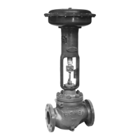
If hoisting the valve, use a nylon sling
to protect the painted surfaces.
Carefully position the sling to prevent
damage to the actuator tubing or any
accessories. Also, take precautions to
prevent personnel from being injured
in case the hoist or rigging slips
unexpectedly. Refer to table 4 for valve
assembly weights and the appropriate
actuator instruction manual for
actuator assembly weights. Be sure to
use adequately sized hoists and
chains or slings to handle the valve
and actuator assembly.
1. Before installing the valve, inspect it to ensure
that the valve body cavity is free of foreign material.