DVC5000 Series
November 1999
3-2
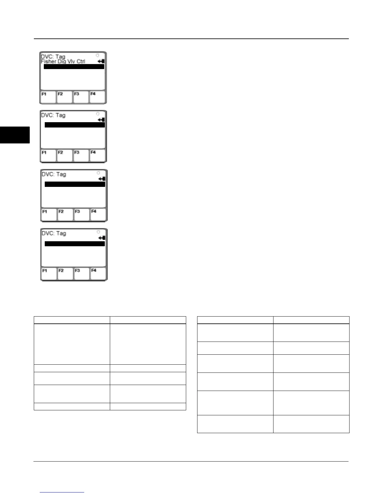
Figure 3-2. Accessing the Setup Wizard on the Model 275 HART Communicator
From the DVC5000 online menu,
select Main Menu.
2 Detailed Setup
3 Display
4 Calibrate
5 Stroke Output
Main Menu (Setup)
From the Main Menu, select Initial
Setup.
From the Auto Setup menu, se-
lect Setup Wizard and follow the
on-line instructions.
2 Manual Setup
Initial Setup
2 Auto Calib Travel
Auto Setup
1'Setup Wizard
3 Stabilize/Optimize
From the Initial Setup menu, select
Auto Setup.
1'Initial Setup
1'Main Menu
2 Analog In12.42 mA
3 Pressure 10 psi
4 Travel 53.69%
5 Drive Sgl 58.15%
1'Auto Setup
Table 3-1. Actuators Available with Setup Wizard
Manufacturer Actuator Model
Fisher Controls
513 and 513R
585C and 585CR
657 and 667
1051 or 1052
1066SR
1250 and 1250R
System 9000
Baumann All
Gulde
3024
3025
Masoneilan
Camflex II
Sigma F, Minitorque
and Ball II
Neles-Jamesbury Quadra-Power II
Table 3-2. DVC5000 Series Factory Default Settings
Setup Parameter Default Setting
Analog Input Units
Input High
Input Low
mA
20.0 mA
4.0 mA
Travel Range High
Travel Range Low
100%
0%
Control Mode
Restart Control Mode
Self-Test Shutdown
Analog (RSP)
Resume Last
All Failures Disabled
Dynamic Bypass Enabled
Input Filter Time
Input Characteristic
No
0 secs
Linear
Travel Limit High
Travel Limit Low
Travel Cutoff High
Travel Cutoff Low
125%
–25%
99.5%
0.5%
Minimum Opening Time
Minimum Closing Time
Polling Address
0 secs
0 secs
0
3
 Loading...


