Maintenance
November 1999
4-3
9. For sliding-stem applications only, install the
protective shield (key 102) onto the side of the
replacement module base assembly.
Submodule Maintenance
The digital valve controller’s master module contains
the following submodules: I/P converter, printed wiring
board assembly, and pneumatic relay. If problems
occur, these submodules may be removed from the
master module and replaced with new submodules.
After replacing a submodule, the master module may
be put back into service.
Note
If the printed wiring board assembly or I/P
converter submodule is replaced, calibrate
and configure the DVC5000 Series digital
valve controller to maintain accuracy
specifications. If any other submodule
was replaced, recalibration or adjustment
of the digital valve controller, master mod-
ule, or submodules is not necessary.
Exercise care when you perform mainte-
nance on the master module. Reinstall the
cover to protect the I/P converter and
gauges when servicing other submodules.
I/P Converter
Refer to figure 4-1 for part identification. The I/P
converter is located on the front of the master module.
Replacing the I/P Filter
A screen in the supply port beneath the I/P converter
serves as a secondary filter for the supply medium. To
replace this filter, perform the following procedure:
1. Remove the I/P converter and shroud as described
in the Removing the I/P Converter procedure.
2. Remove the screen from the supply port.
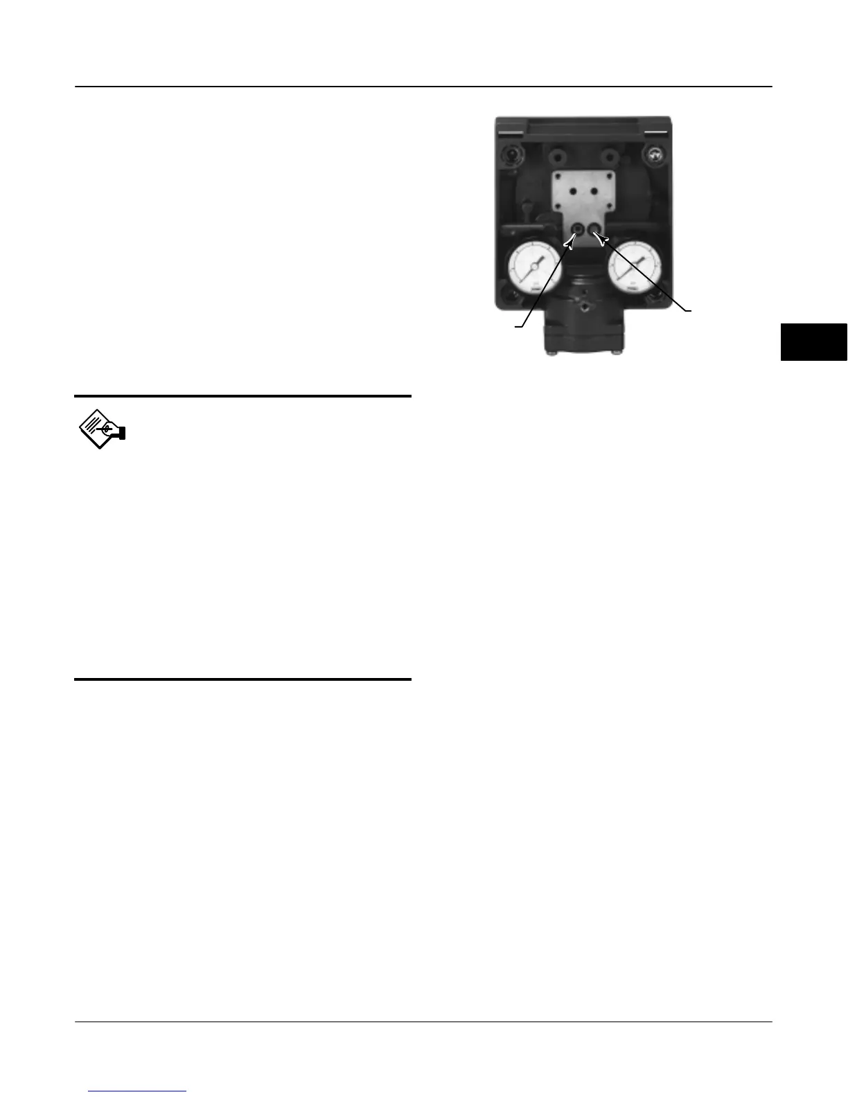
3. Install a new screen in the supply port as shown in
figure 4-3.
SCREEN (FILTER)
LOCATED IN I/P
CONVERTER
SUPPLY PORT
Figure 4-3. I/P Filter Location
O-RING LOCATED
IN I/P CONVERTER
OUTPUT PORT
W7601 / IL
4. Inspect the O-ring in the I/P output port. if
necessary, replace it.
5. Reinstall the I/P converter and shroud as described
in the Replacing the I/P Converter procedure.
Removing the I/P Converter
1. Remove the front cover, if not already removed.
2. Refer to figure 4-4. Remove the four socket-head
screws that attach the shroud and I/P converter to the
module base.
3. Remove the shroud; then pull the I/P converter
straight out of the module base. Be careful not to
damage the two electrical leads that come out of the
base of the I/P converter.
4. Ensure that the O-ring and screen stay in the
module base and do not come out with the I/P
converter.
Replacing the I/P Converter
1. Refer to figure 4-3. Inspect the condition of the
O-ring and screen in the module base. Replace them,
if necessary. Apply sealant to the O-rings.
2. Ensure the two boots shown in figure 4-4 are
properly installed on the electrical leads.
3. Install the I/P converter straight into the module
base, taking care that the two electrical leads feed into
the guides in the module base. These guides route the
leads to the printed wiring board assembly submodule.
4. Install the shroud over the I/P converter.
5. Install the four socket-head screws and evenly
tighten them in a crisscross pattern to a final torque of
20.7 lbfSin (2 NSm).
4
 Loading...


