Installation
Page 44
3. Indoor Unit Installation
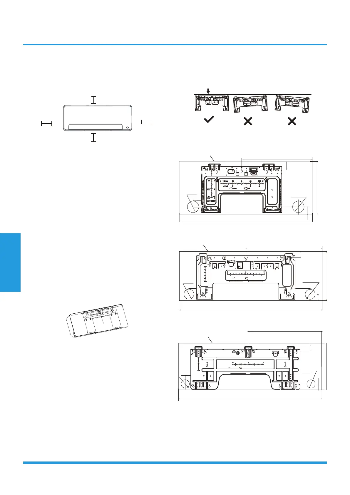
3.1 Service space for indoor unit
12cm (4.72in)
or more
2.3m (90.55in) or more
12cm (4.72in)
or more
Distance from ceiling is determinded
by the installation method.
• If no need the back holder to prop up the unit:
Finishing the pipe and cable connections before mount the
indoor unit on the wall. If the instllation height is limited,
5cm from the ceiling is allowable, but this can lower
product performance. To ensure enough space to install
and remove the top air filter, keep at least 10cm or more
from the ceiling.
• Need the back holder to prop up the unit:
If connecting pipe and cable with front panel open,
the minimum distance from ceiling is 22cm or more, if
connecting pipe and cable without front panel(remove it) ,
the minimum distance from ceiling is 11cm or more.
3.2 Attach mounting plate to wall
• The mounting plate is the device on which you
will mount the indoor unit.
1. Remove the screw that attaches the mounting plate to
the back of the indoor unit.
Screw
2. Secure the mounting plate to the wall with the screws
provided. Make sure that mounting plate is flat against
the wall.
3. Drill holes for mounting screws in places that:
• have studs and can support the weight of the unit.
• correspond to screw holes in the mounting plate.
4. Secure the mounting plate to the wall with the screws
provided.
5. Make sure that mounting plate is flat against the wall.
• Mounting plate dimensions
Different models have different mounting plates. For
the different customization requirements, the shape of
the mounting plate may be slightly different. But the
installation dimensions are the same for the same size of
indoor unit.
Correct orientation of Mounting Plate
FROM EDGE TO HOLE CENTER:50mm
FROM EDGE TO HOLE CENTER:100mm
150
100
100
100
50
50
50
2
2
2
4
4
4
6
RECOMMAND
LIQUID
GAS
BUBBLE
LEVEL
mm
inch
mm
inch
FROM EDG
E
TO HOLE CENTER:50mm
FROM EDGE TO HOLE
CENTE
R:100mm
150
10
0
100
100
50
50
50
2
2
2
4
4
4
6
RECOMMAND
LIQUID
GA
S
BUBBLE
LEVEL
mm
inch
mm
inch
FROM EDGE TO HOLE CENTER:50mm
FROM E
DGE TO
HOL
E CENTER:100mm
150
100
10
0
100
50
50
50
2
2
2
4
4
4
6
RECO
MM
AND
LIQUI
D
GA
S
BUBBLE
LEVEL
mm
inch
mm
inch
9k, 12k
Indoor unit outline
795(31)
120(4.7)
pipe hole
65(2.5)
50(1.9)
pipe hole
65(2.5)
425(16.7)
295(11.6)
51(2.0)
40(1.6)
18k
FROM EDGE TO HOLE CENTER:50mm
FROM EDGE TO HOLE CENTER:95mm
150
100
100
965(38)
50(1.9)
95(3.7)
pipe hole
65(2.5)
pipe hole
65(2.5)
490(19.3)
322(12.7)
40(1.6)
40(1.5)
100
50
50
50
2
2
2
4
4
4
6
RECOMMAND
LIQUID
GAS
BUBBLE
LEVEL
mm
inch
mm
inch
Indoor unit outline
24k
FROM EDGE TO HOLE CENTER:50mm
FROM EDGE TO HOLE CENTER:70mm
570.7(22.5)
70(2.8)
1140(44.8)
50(1.9)
pipe hole
65(2.5)
pipe hole
65(2.5)
370(14.6)
50(1.9)
60(2.4)
BUBBLE
LEVEL
150
100
50
2
4
6
RECOMMAND
mm
inch
100
100
50
50
2
2
4
4
LIQUID
GAS
mm
inch
Indoor unit outline
• Note for concrete or brick walls:
If the wall is made of brick, concrete, or similar material,
drill 5mm-diameter (0.2in-diameter) holes in the wall
and insert the sleeve anchors provided. Then secure the
mounting plate to the wall by tightening the screws
directly into the clip anchors.
 Loading...