Installation
Page 45
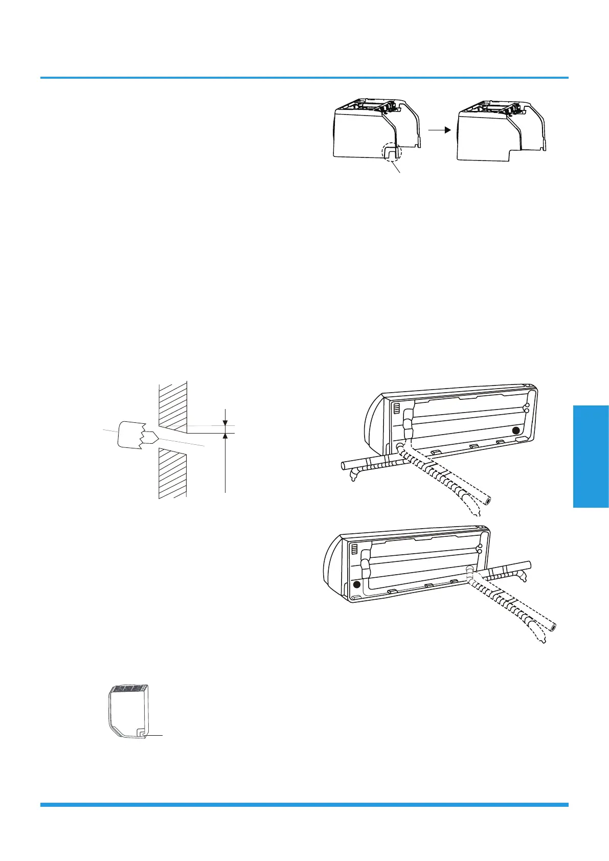
3.3 Drill wall hole for connective piping
You must drill a hole in the wall for refrigerant piping, the
drainage pipe, and the signal cable that will connect the
indoor and outdoor units.
1. Determine the location of the wall hole based on the
position of the mounting plate. Refer to Mounting Plate
Dimensions.
2. Using a 65mm (2.5in) or 90mm(3.54in) (depending on
models )core drill, drill a hole in the wall. Make sure that
the hole is drilled at a slight downward angle, so that the
outdoor end of the hole is lower than the indoor end by
about 5mm to 7mm (0.2-0.27in). This will ensure proper
water drainage.
3. Place the protective wall cuff in the hole. This protects
the edges of the hole and will help seal it when you finish
the installation process.
NOTE: When drilling the wall hole, make sure to avoid
wires, plumbing, and other sensitive components.
Wall
Indoor Outdoor
m
m7
-5
(0.2-0.27in)
3.4 Prepare refrigerant piping
The refrigerant piping is inside an insulating sleeve
attached to the back of the unit. You must prepare the
piping before passing it through the hole in the wall.
1. Based on the position of the wall hole relative to the
mounting plate, choose the side from which the piping will
exit the unit.
2. If the wall hole is behind the unit, keep the knock-out
panel in place. If the wall hole is to the side of the indoor
unit, remove the plastic knock-out panel from that side of
the unit.
Knock-out Panel
(cut depending on the
actual size needed)
If need to cut the big size plastic
panel, cut as shown above.
3. If existing connective piping is already embedded in the
wall, proceed directly to the Connect Drain Hose step. If
there is no embedded piping, connect the indoor unit’s
refrigerant piping to the connective piping that will join the
indoor and outdoor units. Refer to the Refrigerant Piping
Connection section of this manual for detailed instructions.
NOTE: Refrigerant piping can exit the indoor unit from
four different angles:
• Left-hand side
• Left rear
• Right-hand side
• Right rear
Be extremely careful not to dent or damage the piping
while bending them away from the unit. Any dents in the
piping will affect the unit’s performance.
3.5 Connect drain hose
By default, the drain hose is attached to the left
hand side of unit (when you’re facing the back
of the unit).
 Loading...