Instruction Manual
D103175X012
GX Valve and Actuator
July 2017
21
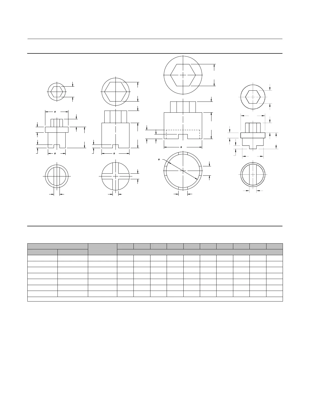
Figure 5. Seat Ring Removal and Installation Tool
GE02918‐6
A
A
G
B
B
H
DF
E
CC
C
D
F
E
DN15, 20, 25
(NPS 1/2, 3/4, 1)
DN40, 50, 80, 100
(NPS 1‐1/2, 2, 3, 4)
A
B
E
F
C
C
J
K
D
DN150
(NPS 6)
DN25 Cav III
(NPS 1)
GG01215
C
OF
OG
D
E
H
B
A
Table 12. Seat Ring Removal and Installation Tool Dimensions
Valve Size
Part Number
A B C D E
FO GO
H
JO
K
DN NPS mm
15, 20, 25 1/2, 3/4, 1 GE02918X012 24 15 15.2 9 54 40 45 10 ‐ ‐ ‐ ‐ ‐ ‐
25 (Cavitrol III) 1 (Cavitrol III) Not Available 24 18 13 6 30 39 45 10 ‐ ‐ ‐ ‐ ‐ ‐
40
(1)
1‐1/2
(1)
GE02918X022 36 20 2X 13.2 7.5 58 53 ‐ ‐ ‐ ‐ ‐ ‐ ‐ ‐ ‐ ‐ ‐ ‐
50
(1)
2
(1)
GE02918X032 46 28 2X 13.2 7.5 63 63 ‐ ‐ ‐ ‐ ‐ ‐ ‐ ‐ ‐ ‐ ‐ ‐
80 3 GE02918X042 60 36 2X 15.2 8.5 100 93 ‐ ‐ ‐ ‐ ‐ ‐ ‐ ‐ ‐ ‐ ‐ ‐
100 4 GE02918X052 70 44 2X 17.2 9.5 114 113 ‐ ‐ ‐ ‐ ‐ ‐ ‐ ‐ ‐ ‐ ‐ ‐
150 6 GE02918X062 100 50 2X 43 10.5 170.5 174 ‐ ‐ ‐ ‐ ‐ ‐ 153 20
1. Also used for Cavitrol III cage removal.
b. Use a torque gun or driver having sufficient torque capabilities according to table 8. Connect the gun to a socket
that snugly fits the hex head on the seat ring tool.
c. Insert the socket onto the hex head of the seat ring tool.
 Loading...


