EasyManua.ls Logo

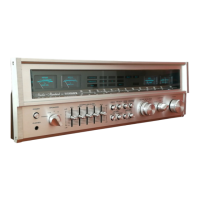
Fisher RS-2010 - Tape Monitor Switches

Fisher RS-2010
14 pages
To Next Page IconTo Next Page
To Previous Page IconTo Previous Page
Loading...
RECEIVER
h
which
you
would
normally
use
them.
Follow
the
instructions
bn
of
the
unit
in
a
very
short
time.
The
frequency
bands
controlled
by
the
five
slide
controls
with
stepped
detents
have
been
chosen
to
yield
the
maxi¬
mum
possible
control
action
within
the
audio
spectrum.
50
Hz
The
50
Hz
control
is
very
useful
in
enhancing
low
bass
notes
as
in
organ
music,
and
it
also
offers
the
possi¬
bility
to
make
corrections
when
a
deficiency
in
bass
exists,
caused
either
by
a
listening
room
with
poor
acoustic
properties
like
bass
absorbing
curtains,
carpets
and
furni¬
ture,
or
by
a
component
part
of
your
system
like
a
speaker,
cartridge
or
record
with
a
poor
bass
response.
250
Hz
The
250
Hz
control
will
allow
you
to
vary
the
upper
bass
frequencies.
1
kHz
The
1
kHz
control
is
the
presence
control
and
can
be
used
very
effectively
to
emphasize,
bring
out
front,
or
de-emphasize
vocalists.
4.5
kHz
The
4.5
kHz
control
will
add
brilliance
and
clarity
to
brass
instruments
and
violins.
15
kHz
The
15
kHz
control
can
be
used
to
make
up
for
missing
high
frequencies
absorbed
by
the
environment
and
to
add
a
natural
crispness
to
music.
0
EQUAL
Switch
In
the
OFF
position,
the
GRAPHIC
EQUALIZER
controls
are
disconnected
and
a
perfectly
flat
frequency
response
is
obtained.
Set
it
to
the
ON
position,
to
bring
GRAPHIC
EQUALIZER
controls
into
operation.
0
TUNING
Knob
If
you
have
selected
FM
or
AM
in
step
2,
tune
in
the
desired
station.
0
FM
STEREO
Indicator
With
the
FUNCTION
switch
in
the
FM
position,
the
indi¬
cator
will
light
when
an
FM
stereo
broadcast
is
received.
If
the
indicator
does
not
light
during
the
reception
of
an
FM
stereo
program,
this
indicates
insufficient
signal
strength.
Flashing
of
the
indicator
is
due
to
spurious
interference.
Neither
phenomenon
indicates
any
problem
with
the
unit.
0
SIGNAL-STRENGTH
Meter
Maximum
deflection
of
the
meter
pointer
indicates
that
an
AM
or
FM
station
is
tuned
in
with
optimum
accuracy.
0
CENTER-OF-CHANNEL
Meter
Turn
the
tuning
knob
and
observe
first
the
pointer
of
the
signal-strength
meter
for
maximum
deflection
to
the
right.
Then
turn
the
tuning
knob
very
slowly
until
the
pointer
of
the
CENTER-OF-CHANNEL
meter
is
in
the
center
of
the
scale
within
the
gap.
0
SPEAKERS
Switch
Set
the
SPEAKERS
switch
to
A
or
B
or
C
or
A+B
positions,
depending
on
the
rear
terminals
to
which
your
speaker
system
is
connected.
Use
the
PHONES
position
when
you
intentionally
want
to
turn
off
your
speakers
(to
listen
privately
through
headphones,
or
to
silence
the
music
system
momentarily,
etc.).
0
POWER
Meters
The
power
meters
indicate
the
approximate
music
program
power
output
levels
delivered
to
the
speaker
systems.
The
power
meters
may
also
be
used
for
continuous
system
monitoring
where
they
provide
an
instantaneous
indication
of
left
and
right
channel
power
distribution
and
channel
balance.
0
LOUDNESS
CONTOUR
Switch
Set
this
button
to
the
ON
or
OFF
position
as
desired.
Pressing
it
to
the
ON
position
will
restore
tonal
balance
and
brilliance
at
normal
and
lower
volume
levels.
0
MONO
MODE
Switch
The
only
times
you
will
have
to
press
the
MONO
MODE
button
are:
When
listening
to
the
occasional
FM
stereo
broadcast
that
sounds
noisy
and
causes
erratic
STEREO
Light
blinking
with
the
MONO
MODE
button
out.
When
playing
a
mono
auxiliary
source
or
mono
record
through
the
receiver.
0
FM
MUTE
Switch
Keep
this
button
in
the
ON
position
to
silence
between-
station
noise
and
weak,
noisy
FM
stations.
Push
this
button
in,
to
the
OFF
postion
only
when
you
wish
to
listen
to
such
stations.
0
FM
MPX
FILTER
Switch
Push
this
button
in,
to
the
ON
position
to
reduce
noise
interference
during
FM
stereo
program
reception.
0
SUBSONIC
FILTER
Switch
Push
this
button
in,
to
the
ON
position
only
when
playing
old
phonograph
records
which
contain
rumble,
or
when
using
a
record
player
which
produces
low-frequency
noise.
At
all
other
times
this
button
should
be
set
to
the
OFF
position.
0
TAPE
MONITOR
Switches
Keep
these
buttons
in
the
SOURCE
position
so
that
you
do
not
accidentally
silence
any
program
source
chosen
with
the
FUNCTION
switch.
Push
the
TAPE
MONITOR
1
button
in,
to
the
TAPE
position
only
when
you
wish
to
play
back
or
monitor
tapes
from
a
tape
recorder
or
deck
connected
to
the
receiver’s
TAPE-1
IN
jacks.
Push
the
TAPE
MONITOR
2
button
in,
to
the
TAPE
position
only
when
you
wish
to
play
back
or
monitor
tapes
from
a
tape
recorder
or
deck
connected
to
the
receiver’s
TAPE-2
IN
jacks.
Push
the
TAPE
MONITOR
1
button
in,
to
the
TAPE
position
and
release
the
TAPE
MONITOR
2
button
out,
to
the
SOURCE
position
when
you
wish
to
duplicate
from
a
tape
recorder
or
deck
(in
the
playback
mode)
connected
to
the
receiver’s
TAPE-1
jacks
to
a
tape
recorder
or
deck
(in
the
recording
mode)
connected
to
the
receiver’s
TAPE-2
jacks.
0
PHONES
Jack
For
private
listening
insert
STEREO
HEADPHONES.
(See
page
6
for
details.)

Related product manuals