Do you have a question about the FlaktWoods STOF and is the answer not in the manual?
Covers compliance with EG Machinery Directive and general safety regulations for operation.
Explains the meaning of the safety symbol indicating danger and risks to personnel.
Details the components of the uninsulated vertical discharge roof fan.
Lists components for the insulated vertical discharge fan version.
Lists components for the uninsulated horizontal discharge fan version.
Describes fan applications and details motor types, construction, and input voltage.
Provides dimensional data and weights for vertical discharge fan versions.
Provides dimensional data and weights for horizontal discharge fan versions.
Procedures for inspecting fans after transport and safety during transport.
Recommendations for storing fans before or between uses, including environmental conditions.
Explains the correct method for lifting the fan, referencing lifting lugs.
Steps for installing the fan on a roof curb (BOGA E130), sizes 225 onwards.
Instructions for mounting the fan onto a base frame using an installation frame.
Important points for electrical connections and safety during installation.
Presents wiring diagrams for 230V and 400V AC/EC motor configurations.
Wiring diagrams specifically for EC motors with BMS and alarm relay.
Wiring diagrams for 400V EC motors with BMS system and alarm relay.
Pre-operation checks for fan installation and safety equipment.
Steps for conducting a test run to verify rotation direction and smooth operation.
Information on fan service requirements, warranty conditions, and authorized personnel.
Steps for cleaning the impeller, motor, and casing for uninsulated versions.
Steps for cleaning the impeller, motor, and casing for insulated vertical versions.
Procedures for replacing the motor and impeller package for uninsulated fans.
Procedures for replacing the motor and impeller package for insulated fans.
Guidance on how to scrap the fan, identifying recyclable components.
Official declaration of conformity with relevant EC directives and harmonized standards.
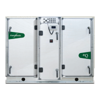
The Fläkt Woods STOF Roof Fan is designed to generate the required airflow in ventilation systems, overcoming pressure drops in the duct system through the use of a rotating impeller within the fan casing. These fans are primarily used as exhaust fans in ventilation systems.
The STOF Roof Fan is available in both uninsulated and insulated vertical discharge versions, as well as an uninsulated horizontal discharge version.
Construction (Uninsulated Vertical Discharge - Sizes 355 to 630):
Construction (Insulated Vertical Discharge):
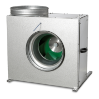
Construction (Uninsulated Horizontal Discharge):
Motors: The fans are equipped with either 1- or 3-phase external rotor motors with integrated impellers. EC-motors also feature an integrated speed controller. Detailed motor information, including minimum and maximum allowed temperatures, is available in the technical catalogue.
| Fan size | Motor type | Motor construction | Input voltage |
|---|---|---|---|
| 190 - 400 | AC | Outer rotor | 1~230 VAC |
| 355 - 630 | AC | Outer rotor | 3~400 VAC |
| 190 - 400 | EC | Outer rotor | 1~230 VAC |
| 450 - 630 | EC | Outer rotor | 3~400 VAC |
Dimensions and Weight (Uninsulated Vertical Version):
| Fan size | A | A1 | H | Lin | Lout | Win | Wout | Weight |
|---|---|---|---|---|---|---|---|---|
| 190 | 245 | 130 | 358 | 348 | 8 | |||
| 225 | 328 | 226 | 447 | 467 | 447 | 469 | 10 | |
| 310 | 328 | 306 | 447 | 467 | 447 | 469 | 16 | |
| 355 | 438 | 341 | 557 | 577 | 557 | 579 | 22 | |
| 400 | 508 | 351 | 627 | 647 | 627 | 649 | 27 | |
| 450 | 598 | 382 | 717 | 737 | 717 | 739 | 36 | |
| 500 | 778 | 461 | 897 | 917 | 897 | 919 | 56 | |
| 630 | 998 | 520 | 1117 | 1137 | 1117 | 1139 | 82 |
Dimensions and Weight (Insulated Vertical Version):
| Fan size | A | A1 | H | Lin | Lout | Win | Wout | Weight |
|---|---|---|---|---|---|---|---|---|
| 225 | 328 | 505 | 447 | 465 | 447 | 500 | 24 | |
| 310 | 328 | 505 | 447 | 465 | 447 | 500 | 24 | |
| 355 | 438 | 555 | 557 | 570 | 557 | 610 | 36 | |
| 400 | 508 | 606 | 630 | 644 | 630 | 675 | 38 |
Dimensions and Weight (Horizontal Version):
| Fan size | A | A1 | H | Win | Wout | Hout | Weight |
|---|---|---|---|---|---|---|---|
| 190 | 245 | 216 | 345 | 480 | 7 | ||
| 225 | 328 | 261 | 447 | 480 | 10 | ||
| 310 | 328 | 340 | 447 | 480 | 14 | ||
| 355 | 438 | 383 | 557 | 600 | 18 | ||
| 400 | 508 | 398 | 627 | 710 | 411 | 24 | |
| 450 | 598 | 433 | 717 | 820 | 441 | 32 | |
| 500 | 778 | 527 | 897 | 1030 | 540 | 53 | |
| 630 | 998 | 595 | 1117 | 1300 | 597 | 76 |
Installation: The fan can be installed either with a roof curb (BOGA E130) or by using an installation frame on a separately built base frame.
Electrical Connections: All electrical installations must be carried out by authorized personnel, following local safety regulations. An isolator must be included in the mains cable, and the motor should be protected with motor protection if necessary. Cable and fuses must be dimensioned according to local requirements, and contact between cables and the impeller must be prevented.
Commissioning: Before starting, check for any abnormal devices inside the fan, verify correct installation, and ensure all safety equipment is in place. During a test run, check for correct rotation direction, smooth impeller rotation, and absence of abnormal noises.
General Service: The roof fan generally requires no special service, but regular cleaning of the impeller is necessary, especially if the air is not clean, to prevent vibrations. If abnormal noise from motor bearings occurs, the motor and impeller or the complete fan unit should be replaced.
Warranty: Warranty is contingent on proper installation and necessary service actions being performed. Any problems during the warranty period should be reported to the manufacturer or dealer.
Cleaning and Motor Replacement:
Uninsulated Versions (Sizes 225-630):
Insulated Vertical Version:
Motor Replacement (Uninsulated Version):
Motor Replacement (Insulated Version):
Scrapping: Electrical motors and other electrical components must be removed from the fan according to their specific instructions. Steel material is recyclable, as are the small plastic components within the fan.
| Brand | FlaktWoods |
|---|---|
| Model | STOF |
| Category | Fan |
| Language | English |