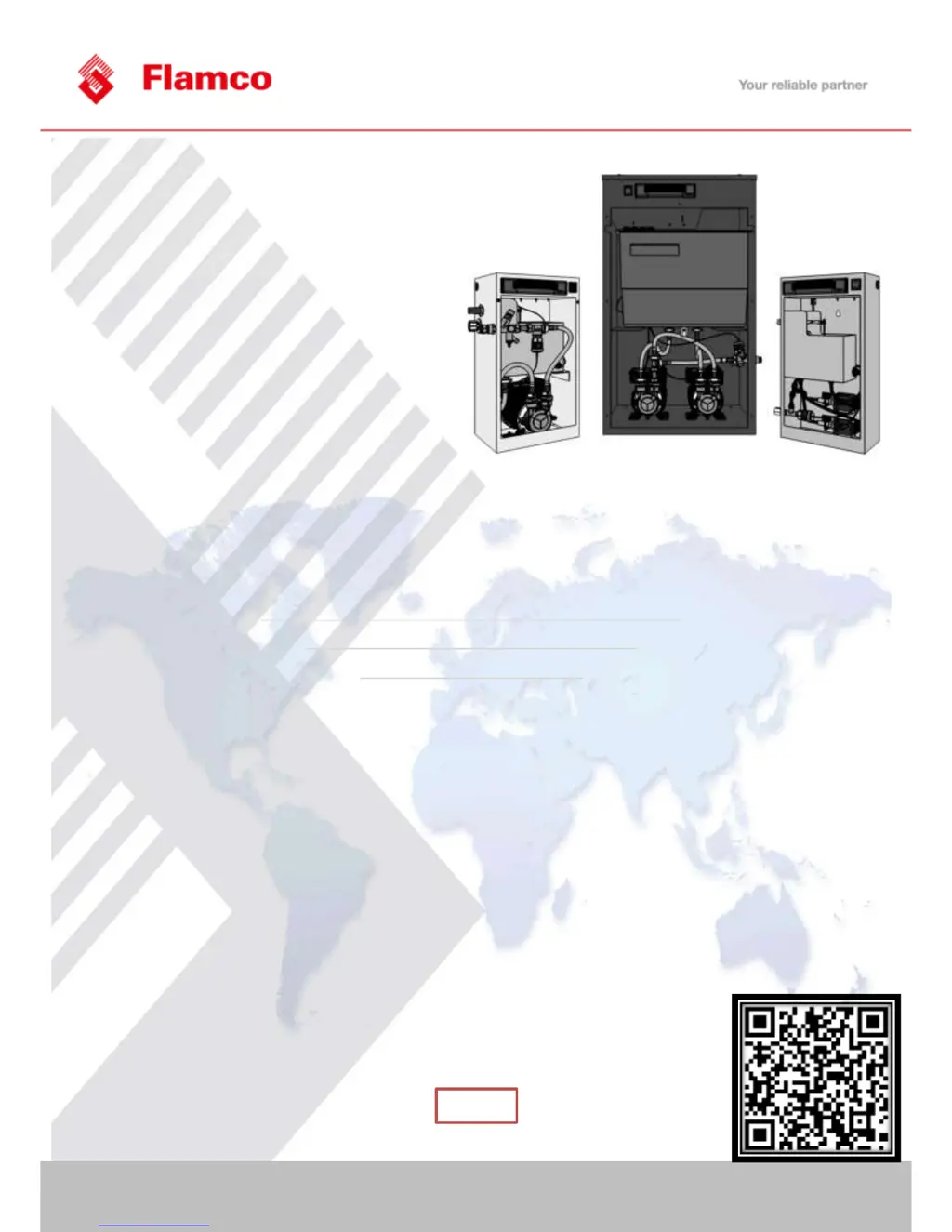
EasyManua.ls Logo

flamco Flexfiller 125D User Manual

flamco Flexfiller 125D
44 pages
To Next Page IconTo Next Page
Page #1 background imageLoading...
Page #1 background image
www.flamcogroup.com
© 2014 Flamco group. All rights reserved.
We reserve the right to change designs and technical specifications of our products.
Rev 8.1 Aug-15 Page 1 / 44
Flexfiller Digital Pressurisation Equipment
Flexfiller Models (125D, 225D, 150D, 250D, 280D)
Midi Models (125D, 225D, 150D, 250D)
Mini Models (130D, 230D)
Operation & Maintenance
Manual
Rev 8.3

Questions and Answers:

flamco Flexfiller 125D Specifications

General IconGeneral
Brandflamco
ModelFlexfiller 125D
CategoryPortable Generator
LanguageEnglish

Summary

About this Manual

Conventions used in this Manual

Explains symbols and terminology used within the manual for clarity and safety.

Typography

Details the use of different text styles like italics and brackets to convey specific information types.

Where to find more Information

Provides contact details and website for additional product information and support.

Equipment Overview

Principal of Operation

Describes the fundamental working mechanism of the Flexfiller pressurisation unit and its components.

Installation

Pipe Connections

Details the requirements and considerations for making pipe connections to the pressurisation unit.

Typical Installation Diagram

Illustrates the recommended physical layout and connection points for installing the unit.

Flow Restrictors (Mini & Midi Models Only)

Guides on selecting and fitting the correct flow restrictor based on mains water pressure.

Flexfiller Clearance and Connection Requirements

Specifies minimum clearances and connection details for the Flexfiller model.

Midi Clearance and Connection Requirements

Specifies minimum clearances and connection details for the Midi model.

Mini Clearance and Connection Requirements

Specifies minimum clearances and connection details for the Mini model.

Electrical Power Supply

Outlines the correct and safe methods for connecting the unit to the electrical mains supply.

Fault Contacts

Details the available volt-free fault contacts for BMS integration or boiler interlock.

Commissioning

Pre-Commissioning Checklist

Lists essential checks to be completed before starting the commissioning process to ensure safety and functionality.

Controller Overview

Introduces the digital controller, its buttons, and the LED display functions.

Controller Programming

Explains how to access and navigate the controller's programming menu to adjust settings.

Program List

Provides a detailed breakdown of all programmable menu items, their functions, and default values.

Hydraulic Commissioning

Outlines the step-by-step procedure for the hydraulic setup and initial filling of the unit.

Operation

Fault Codes

Lists and explains all error codes displayed by the digital controller and their reset methods.

Shutdown procedure

Provides instructions on how to safely shut down the pressurisation unit for maintenance or other scenarios.

Start-up Procedure

Details the steps required to restart the unit after it has been shut down.

Maintenance

Visual Inspection

Describes essential visual checks to identify potential faults and ensure unit integrity.

Interrogate Controller

Explains how to access and interpret logged data from the digital controller for diagnostics.

Test Unit Operation

Details methods to test the unit's functionality by simulating pressure drops and pump activation.

Check Float Valve Operation

Guides on testing the break tank float valve's functionality and response to water level changes.

Check Float Switch Operation

Explains how to test the low-level float switch and its effect on the controller display.

Check Break Tank Water Condition

Advises on inspecting the break tank for cleanliness and the presence of debris.

Check Strainer (Flexfiller units only)

Outlines the procedure for inspecting and cleaning the mesh strainer specific to Flexfiller models.

Check Expansion Vessel Pre-Charge

Details the importance and method for checking the expansion vessel's pre-charge pressure.

Wiring Diagram

Provides a detailed electrical schematic showing the internal wiring connections of the pressurisation unit.

Wiring location list

Lists the colour coding and terminal connections for various components within the electrical box.

Spares

Flexfiller Models (125D, 250D, 150D, 280D)

Lists the part codes for components specific to Flexfiller models.

Midi Models (125D, 250D, 150D, 250D)

Lists the part codes for components specific to Midi models.

Mini Models (130D, 230D)

Lists the part codes for components specific to Mini models.

Troubleshooting

LOW PRESSURE fault is displayed and the pumps do not run

Addresses issues where the unit displays a low pressure fault and the pumps fail to activate.

P1 and/or P2 FAIL is displayed

Provides solutions for pump failure faults (P1 FAIL or P2 FAIL) indicated by the controller.

The break tank is overfilling and discharging water to drain or over the weir

Offers remedies for scenarios where the break tank is losing water through overflow.

Service Logs

Warranty Information

Warranty - What Is Covered?

Specifies the scope of the manufacturer's warranty for the equipment.

Warranty - What Is Not Covered?

Outlines conditions and scenarios that are excluded from the warranty coverage.

Conditions of warranty

Lists the prerequisites and requirements that must be met for the warranty to remain valid.

Contact Details

Provides Flamco's contact information for inquiries, support, and warranty claims.

Related product manuals