Printed in U.S.A.
Page 3B
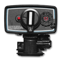
MODEL 6700 Downflow - V2.0
Option Setting Level #2
Programming Chart (Cont’d.)
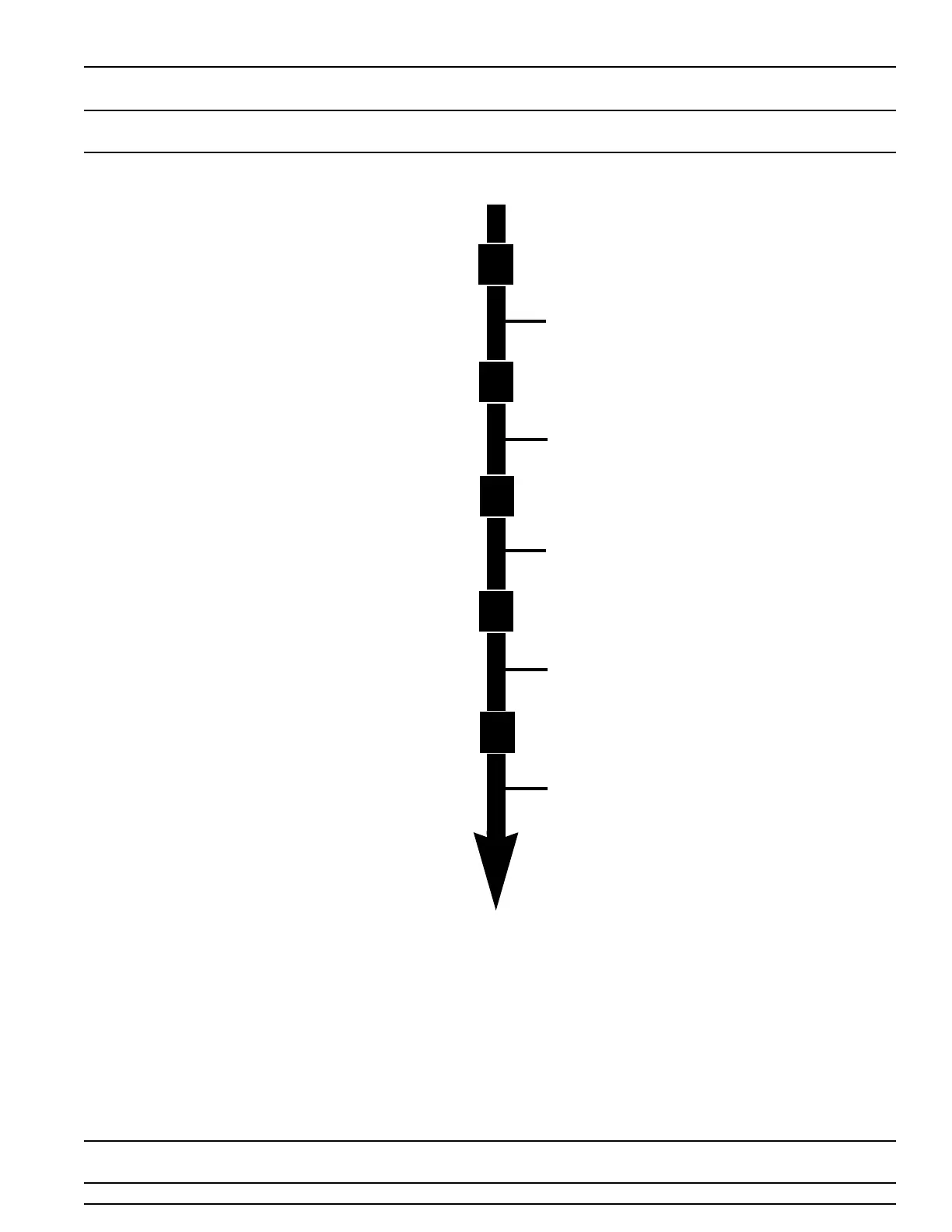
Level #2 - Continued
NOTE:
1. Push Program Button Once Per Display.
2. Option settings may be changed by pushing
either the Up or Down Arrow Button.
3. Depending on current valve programming
certain displays will not be able to be viewed or
set.
Flow Meter Size
Examples: Option Not Typically Used [F - - - - - 0]
Standard 3/4” Flow Meter [F - - - - - 1]
Option Not Typically Used [F - - - - - 2]
Option Not Typically Used [F - - - - - 3]
Option Not Typically Used [F - - - - - 4]
Option Not Typically Used [F - - - - - 5]
Option Not Typically Used [F - - - - - 6]
Mixing Valve Location
Examples: No Mixing Valve [8 - - - - - 1]
Mixing Valve Before Flow Meter [8 - - - - - 2]
Mixing Valve After Flow Meter [8 - - - - - 3]
Note: This Display Only Viewed With Metric Display
Formats U2 & U4
System Type
Examples: Single Valve System #4 Operation [9 - - - - - 4]
Option Not Currently Offered [9 - - - - - 5]
Option Not Currently Offered [9 - - - - - 6]
Option Not Currently Offered [9 - - - - - 7]
Option Not Currently Offered [9 - - - - - 8]
Option Not Currently Offered [9 - - - - - 9]
Program Lock
Examples: Lock Cancelled [PL - - OFF]
Lock Active [PL - - - On]
Option Level # 2 is Exited
Normal Operation is Resumed
Program
Program
Program
Program
Program