

D
David TaylorAug 16, 2025
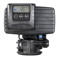
How to fix excessive water in brine tank of Fleck 5600 Water Dispenser?
- CCindy JohnsonAug 16, 2025
If there's excessive water in the brine tank of your Fleck Water Dispenser, consider these possible causes and solutions: * The by-pass valve might be open. Ensure the by-pass valve is closed. * There might be no salt in the brine tank. Add salt to the brine tank, maintaining the salt level above the water level. * The injectors or screen could be plugged. Replace the injectors and screen. * There might be insufficient water flowing into the brine tank. Check the brine tank fill time and clean the brine line flow control if it's plugged.