EasyManua.ls Logo

Fleck 7000 - User Manual

Fleck 7000
36 pages
Print Icon
To Next Page IconTo Next Page
Loading...
Model 7000
Service Manual
IMPORTANT: Fill in Pertinent Information on Page 3 for Future Reference

Other manuals for Fleck 7000

Questions and Answers

  • D
    Donald AndersonJul 26, 2025
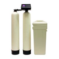
    Why is there excessive water in the brine tank of my Fleck Water Dispenser?
    • C
      Corey DuranJul 26, 2025
      If your Fleck Water Dispenser is experiencing excessive water in the brine tank, possible causes include: * A plugged drain line flow control; check the flow control. * A plugged injector system; clean the injector and screen. * The timer not cycling; replace the timer. * Foreign material in the brine valve; replace the brine valve seat and clean the valve. * Foreign material in the brine line flow control; clean the brine line flow control. * Power loss during brine fill; check the power source.
  • M
    Mason SchaeferJul 30, 2025
    How to fix a Fleck Water Dispenser that fails to regenerate?
    • J
      Jason Beasley PhDJul 30, 2025
      If your Fleck Water Dispenser fails to regenerate, it could be due to: * Interrupted electrical service to the unit. Ensure permanent electrical service by checking the fuse, plug, pull chain, or switch. * A defective timer. If the timer is defective, replace it.
  • L
    lindsaykramerAug 4, 2025
    Why is my Fleck Water Dispenser producing hard water?
    • H
      Hannah CoffeyAug 4, 2025
      If you're experiencing hard water with your Fleck Water Dispenser, there are several potential causes: * The bypass valve might be open; ensure it is closed. * The brine tank may be low on salt; add salt, maintaining the level above the water line. * The injector screen could be blocked; try cleaning it. * Insufficient water flowing into brine tank. Check brine tank fill time and clean brine line flow control if plugged. * There could be a leak at the distributor tube, check if the distributor tube is cracked and inspect the O-ring and tube pilot. * Internal valve leak. Replace seals and spacers and/or piston.
  • K
    Kim FieldsAug 8, 2025
    Why does my Fleck Water Dispenser use too much salt?
    • T
      Tommy BarryAug 9, 2025
      If your Fleck Water Dispenser is using too much salt, it could be due to an improper salt setting. Check the salt usage and the salt setting to ensure they are correctly configured. It may also be caused by excessive water in the brine tank.
  • J
    John JohnsonAug 13, 2025
    What to do if my Fleck Water Dispenser has loss of water pressure?
    • T
      Thomas HooperAug 13, 2025
      If you're experiencing a loss of water pressure with your Fleck Water Dispenser, it could be due to: 1. Iron buildup in the line to the water conditioner; clean the line. 2. Iron buildup in the water conditioner itself; clean the control and add mineral cleaner to the mineral bed, also consider increasing the frequency of regeneration and/or backwash time. 3. The inlet of the control being plugged due to foreign material; remove the pistons and clean the control.
  • C
    Cynthia HenryAug 17, 2025
    Why is my Fleck Water Dispenser losing mineral through the drain line?
    • J
      Jennifer FlemingAug 17, 2025
      If you notice a loss of mineral through the drain line of your Fleck Water Dispenser, it could be caused by: * Air in the water system. Make sure the well system has a proper air eliminator control and check for a dry well condition. * The drain line flow control being too large. Check to ensure the drain line flow control is sized properly for your mineral tank.
  • B
    Brooke LoweAug 21, 2025
    What causes iron in the treated water from my Fleck Water Dispenser?
    • L
      Lisa CraneAug 21, 2025
      If there is iron in the treated water from your Fleck Water Dispenser, it could be due to a fouled mineral bed. Check the backwash, brine draw, and brine tank fill. Increase the frequency of regeneration.

Summary

Job Specification Sheet

Water Softener Control Valve

Water Pressure Requirements

Minimum and maximum water pressure required for the regeneration valve's proper operation.

Electrical Requirements

Details on the necessary alternating current supply and connection considerations.

Installation Site Considerations

Guidance on plumbing condition, softener location, and bypass valve installation.

Valve Installation and Start-Up Procedures

Installation Steps

Step-by-step instructions for the physical installation and initial setup of the control valve.

7000 Control Operation and Settings

Control Display Overview

Explanation of indicators, display elements, and screen information for the controller.

Regeneration Modes Overview

Description of Time Clock, Metered, and Day-of-Week regeneration system types.

Flow Meter Operation Details

Details on delayed regeneration and volume remaining display for flow meter systems.

Control States and Events

System behavior during regeneration, programming, and power failures.

Manual Regeneration Initiation

Procedure for manually starting an extra regeneration cycle.

7000 Control Start-Up Procedures

Setting Time of Day

Procedure to set the current time on the controller display.

Accessing Programming Mode

Steps to enter the control's programming interface.

Understanding Regeneration System Types

Overview of Time Clock, Meter Immediate, Meter Delayed, and Day of Week systems.

Programming a Meter Delayed Regenerated System

Setting Feed Water Hardness

Inputting water hardness for treated water capacity calculation.

Setting Regeneration Time

Configuring the scheduled time of day for regeneration.

Extended Programming: Cycle Step Times

Programming the duration for each regeneration cycle step.

Extended Diagnostics Mode

Viewing diagnostic data like days since last regeneration.

Programming a Meter Immediate Regeneration System

Setting Feed Water Hardness

Inputting water hardness for immediate regeneration systems.

Extended Programming: Cycle Step Times

Programming cycle step durations for immediate regeneration.

Extended Diagnostics Mode

Viewing diagnostic data for immediate regeneration systems.

Programming a Time Clock Regeneration System

Setting Regeneration Time

Configuring the scheduled regeneration time for time clock systems.

Setting Regeneration Day Interval

Defining the number of days between regeneration cycles.

Extended Programming: Cycle Step Times

Programming cycle step durations for time clock regeneration.

Extended Diagnostics Mode

Viewing diagnostic data for time clock regeneration systems.

Programming a Day of the Week Regenerated System

Setting Regeneration Time

Configuring the regeneration time for day-of-week systems.

Setting Current Day of Week

Inputting the current day of the week for system tracking.

Configuring Regeneration Days

Enabling or disabling regeneration for specific days.

Extended Programming: Cycle Step Times

Programming cycle step durations for day-of-week regeneration.

Water Conditioner Flow Diagrams

In Service and Backwash Flow

Diagrams illustrating water flow in service and backwash positions.

Brine and Slow Rinse Flow

Diagrams illustrating water flow in brine and slow rinse positions.

Rapid Rinse and Brine Refill Flow

Diagrams illustrating water flow in rapid rinse and brine refill positions.

Power Head Assembly

Power Head Component Diagram

Exploded view showing the components of the power head assembly.

Power Head Assembly Parts List

Power Head Components Identification

List and identification of parts for the power head assembly.

Valve Assembly

Valve Assembly Diagram

Exploded view showing the components of the main control valve.

Valve and Injector Parts

Detailed parts list for the valve and associated injectors.

Bypass Assembly

Bypass Assembly Diagram and Parts

Exploded view and component list for the bypass assembly.

2310 Safety Brine Valve

Safety Brine Valve Diagram and Parts

Exploded view and component list for the safety brine valve.

Troubleshooting

Error Codes and Recovery Procedures

Explanation of error codes and steps to resolve them.

Common Problems and Corrective Actions

Solutions for issues like salt usage, water pressure, and brine tank problems.

Removing Gear Box Assembly

Gear Box Removal Steps

Procedure for safely removing the gearbox from the unit.

Inserting Circuit Board

Circuit Board Installation Guide

Instructions for correctly installing the circuit board into the unit.

Connecting the Circuit Board

Circuit Board Wiring Connections

Guide for connecting motor, transformer, and meter cables to the circuit board.

Dimensions

Unit Physical Dimensions

Detailed measurements of the unit's size, height, width, and depth.

Meter Flow Data

Service Flow Rate vs. Pressure Drop

Graph showing performance data for different valve types at various pressure drops.

Injector Flow Data

Injector Flow Performance Graphs

Charts detailing injector flow rates under various pressure conditions.

Fleck 7000 Specifications

General IconGeneral
Valve MaterialNoryl
Service Flow Rate12-15 GPM
TypeWater Softener
Flow Rate12-15 GPM
Power Supply120V/60Hz or 220V/50Hz

Related product manuals