Page 2
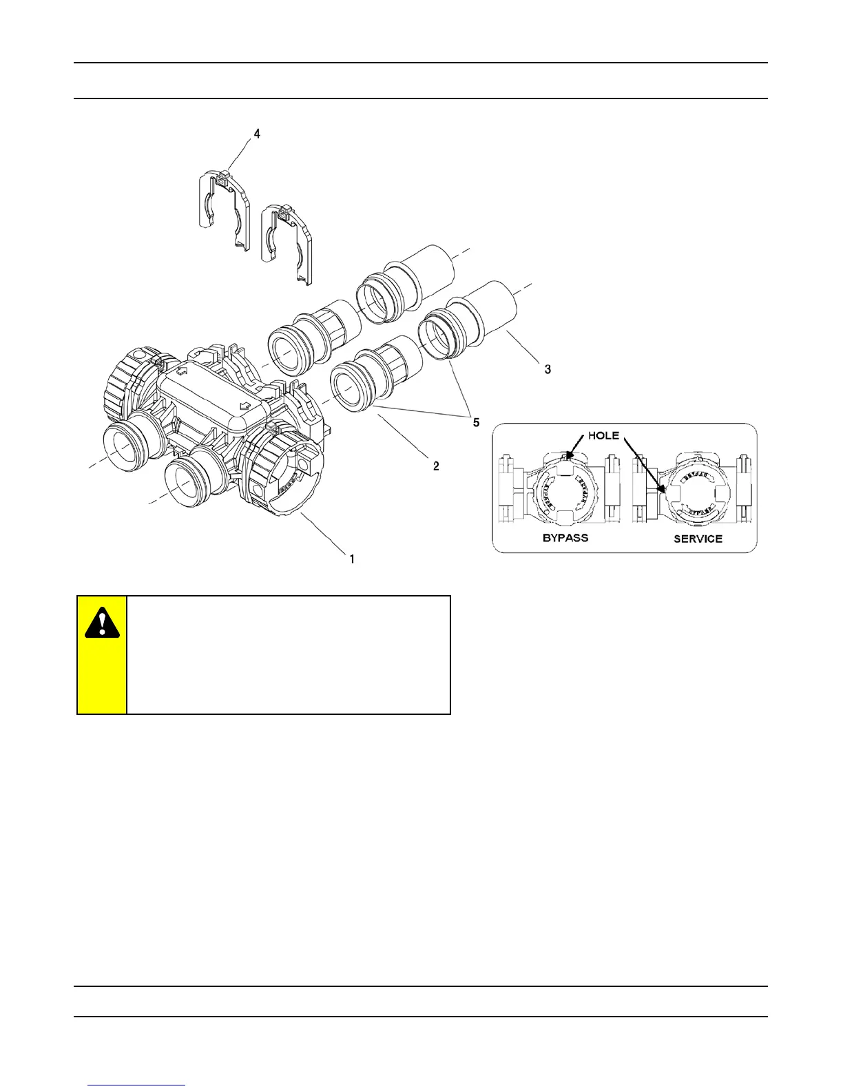
Bypass Assembly
IMPORTANT
To bypass the valve, turn bypass knob on both
sides of the valve to bypass position.
When returning to service, put the inlet into
service before the outlet.
Item No. Quantity Part No. Description
1 ...................... 1 ................. 40569 ................. Bypass Assembly, 7000, Less Clip
2 ...................... 2 ................. 0563-01 ............ Connector Assy, 1” NPT, w/O-ring
0563-11 ............ Connector Assy, 1” BSP, w/O-ring
0565-01 ............ Connector Assy, 1 1/” NPT w/O-ring
0565-11 ............ Connector Assy, 1 1/” BSP w/O-ring
3 ...................... 2 ................. 122-01 ............ Connector Assy, 1” & 1/” Sweat, w/O-ring
123-01 ............ Connector Assy, 1 1/” & 1 1/2” Sweat, w/O-ring
4 ...................... 2 ................. 40576 ................. Clip, H, Plastic, 7000
5 ...................... 1 ................. 40951 ................. O-ring, -220
Not Shown ...... 1 ................. 61462 ................. By-Pass Service Kit, 7000 (Includes all internal parts for
7000 bypass assembly - bypass body not included)