Printed in U.S.A.
Page 17
MODEL 5600 & 5600 ECONOMINDER
®
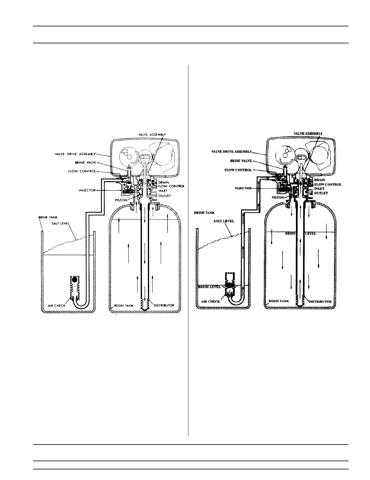
Water Conditioner Flow Diagrams (Cont’d.)
4
BRINE POSITION
3
BACKWASH POSITION
10 Minutes First Portion of 50 Minute Fixed Cycle
Hard water enters the unit at the valve inlet - flows
around the lower piston groove and lower piston land -
down thru the center tube and out the distributor - up
thru the resin - thru the top of tank passage - around
the upper piston groove and out the drain line.
Hard water enters the unit at the valve inlet - flows around
the lower piston groove - thru the injector nozzle and
orifice to draw brine from the brine tank. The brine flows
down thru the resin - into the distributor - up thru the
center tube - thru the center hole in the piston and out the
drain line.