Printed in U.S.A.
Page 16
MODEL 5600 & 5600 ECONOMINDER
®
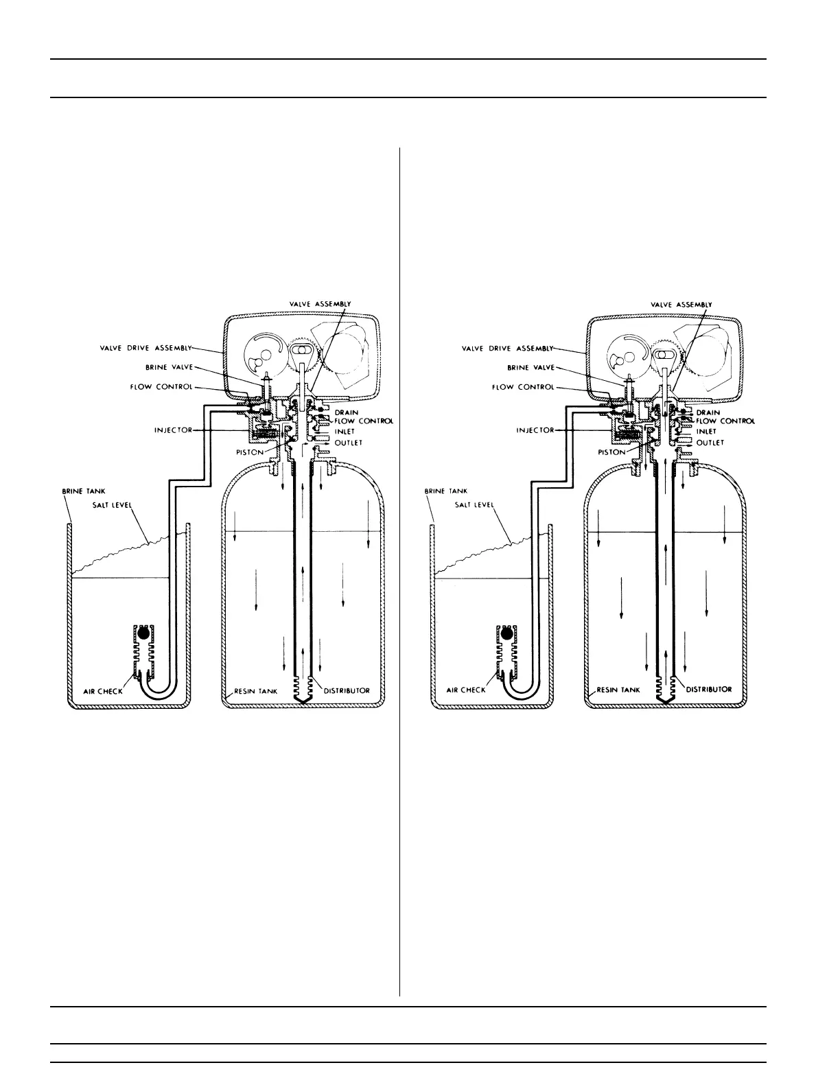
Water Conditioner Flow Diagrams
1
SERVICE POSITION
2
PRELIMINARY RINSE POSITION
Hard water enters the unit at the valve inlet - flows
around the lower piston groove - thru the passage to
the top of tank - down thru the resin and enters the
distributor as conditioned water. The conditioned
water flows up thru the center tube to the valve outlet.
Hard water enters the unit at the valve inlet - flows around
the lower piston groove - down thru the top of tank
passage - downward thru the resin - up the distributor tube
- thru the center hole in the piston - over the top edge of
the piston and out the drain line.
5 Minutes