Printed in U.S.A.
Page 3
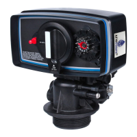
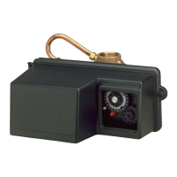
MODEL 9000 ECONOMINDER
General, Residential & Commercial Installation Check List
WATER PRESSURE: A minimum of 25 pounds of water pressure is required for regeneration valve to operate effectively.
ELECTRICAL FACILITIES: A continuous 110 volt, 60 Hertz current supply is required. Make certain the current supply is
always hot and cannot be turned off with another switch.
EXISTING PLUMBING: Condition of existing plumbing should be free from lime and iron buildup. Piping that is built up
heavily with lime and/or iron should be replaced. If piping is clogged with iron, a separate iron filter unit should be installed
ahead of the water softener.
LOCATION OF SOFTENER AND DRAIN: The softener should be located close to a drain.
BY-PASS VALVES: Always provide for the installation of a by-pass valve.
CAUTION: Water pressure is not to exceed 120 p.s.i., water temperature is not to exceed 110° F, and the unit cannot be
subjected to freezing conditions.
1. Place the softener tank where you want to install the unit, making sure the tanks are level and on a firm base.
2. All plumbing should be done in accordance with local plumbing codes. The pipe size for the drain line should be
minimum 1/2″. Overhead drains exceeding 4′ above unit require 3/4″ drain line.
3. Both tanks must be the same height and diameter and filled with equal amounts of media. The 1″ distributor tube
(1.050 O.D.) should be cut flush with top of each tank.
4. Lubricate the distributor O-Ring seal and tank O-Ring seal with silicone lubricant. Place the main control valve on one
tank and the tank adapter on the second tank.
5. NOTE: The 1″ copper tubing to interconnect the tanks must be soldered prior to assembly on the main control valve
and tank adapter. There should be a minimum of 1″ distance between tanks on final assembly.
6. Solder joints near the drain must be done prior to connecting the Drain Line Flow Control fitting. Leave at least 6″
between the DLFC and solder joints when soldering. Failure to do this could cause damage to the drain module.
7. Teflon tape is the only sealant to be used on the drain fitting.
8. Make sure that the floor is clean beneath the salt storage tank and that it is level.
9. Place approximately 1″ of water above the grid plate (if used) in your salt tank. Salt may be placed in the unit at this
time.
10. On units with a by-pass, place in by-pass position. Turn on the main water supply. Open a cold soft water tap nearby
and let run a few minutes or until the system is free from foreign material (usually solder) that may have resulted from
the installation.
11. Place the by-pass in service position and let water flow into the mineral tanks. When water flow stops, open a cold
water tap nearby and let run until air pressure is relieved.
12. Electrical: All electrical connections must be connected according to codes. Plug unit into electrical outlet.
Do not
insert meter cable
into the meter yet.
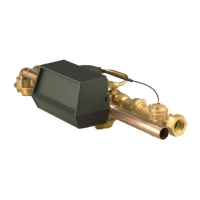
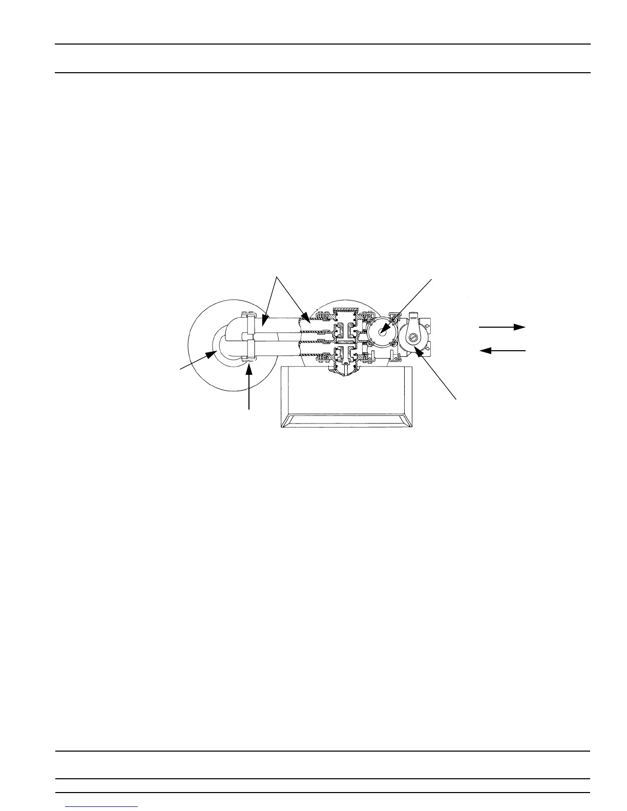
BRASS YOKES
TANK #2 TANK #1
TANK #2 ADAPTER
ADAPTER CLIPS
MAIN CONTROL
VALVE
OUTLET
INLET
Installation and Start-Up Instructions
WATER METER
BY-PASS
VALVE

 Loading...