EasyManua.ls Logo

Fleck 6600 - User Manual

Fleck 6600
205 pages
Print Icon
To Next Page IconTo Next Page
Loading...
6600 – 6665 – 6700 – 6765
6600, 6665,
6700, 6765
6700
6665

Table of Contents

Questions and Answers

  • J
    John SmithAug 17, 2025
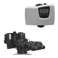
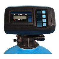
    How to fix a Fleck Control Unit when the softener fails to regenerate?
    • A
      Anna MannAug 17, 2025
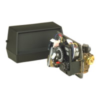
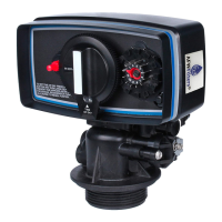
      If your Fleck Control Unit softener isn't regenerating, it could be due to several reasons. First, check for any interrupted power supply by restoring electrics (mains, fuse). A defective power head might be the cause, requiring a replacement. Inspect the meter cable connections on the time rand and meter cover. A blocked meter may also prevent regeneration; clean or replace it. If the motor is defective, consider changing it. Lastly, ensure the programming is correct and modify it if necessary.
  • R
    rebekah54Aug 23, 2025
    Why is my Fleck 6600 using excessive salt?
    • W
      whernandezAug 23, 2025
      Excessive salt consumption in your Fleck Control Unit could stem from a few issues. Check the brine refill setting and salt usage. Too much water in the brine tank can also cause this issue. Also, verify the programming and modify if necessary.
  • N
    Nicole RoachAug 26, 2025
    What to do if there is too much water in the Fleck 6600 Control Unit brine tank?
    • G
      gonzalesdesireeAug 26, 2025
      If there's too much water in your Fleck Control Unit brine tank, it could be due to a plugged drain line flow control (DLFC), a faulty brine valve, or wrong programming. Check the flow regulator, change the brine valve, and verify the programming, modifying it if necessary.
  • V
    Veronica HesterAug 28, 2025
    How to stop constant leakage to the drain from my Fleck 6600?
    • J
      Jose PotterAug 28, 2025
      Constant leakage to the drain in your Fleck Control Unit can be caused by several factors. Foreign elements in the valve could be the culprit; clean the valve and check it in different regeneration positions. An internal valve leak might also be the cause, requiring you to change the seals & spacers and/or piston assembly. The valve might be blocked in brine refill or backwash, also requiring you to change the seals & spacers and/or piston assembly. A defective or blocked timer motor could be responsible; change the motor and check the gear teeth. Lastly, the powerhead might not be operating properly, necessitating a change.
  • T
    Teresa KingAug 31, 2025
    Why is there salted water in the service line of my Fleck Control Unit?
    • J
      James MurrayAug 31, 2025
      Salted water in the service line of your Fleck Control Unit may be due to several reasons. The filter and injector might be blocked, requiring cleaning. The power head may not be operating proper cycles and require replacement. Foreign elements in the brine valve or in the brine line flow control (BLFC) can also cause this; clean the BLFC and change the brine valve seat. Low water pressure could be a factor; raise the inlet pressure to 1,8 bar minimum. Finally, incorrect programming might be the cause; check and modify if necessary.
  • V
    vincentrodriguezSep 2, 2025
    What causes no brine draw in my Fleck 6600?
    • H
      hortonmelissaSep 2, 2025
      If your Fleck Control Unit isn't drawing brine, it could be due to a plugged drain line flow control (DLFC), so clean it. The filter and injectors might be plugged; clean or change them if necessary. Low water pressure can also cause this issue; increase the inlet pressure to 1,8 bar minimum. An internal valve leak may be the problem; change the seals, spacers and/or piston assembly. Incorrect programming could be the cause; check and modify if necessary. Lastly, the power head might not be operating properly, requiring a replacement.
  • C
    Christian AverySep 5, 2025
    Why is there a water pressure drop in my Fleck 6600?
    • D
      david88Sep 5, 2025
      A water pressure drop in your Fleck Control Unit could be due to iron deposits in the softener inlet or within the softener itself. Clean the inlet, valve, and resin. Another cause might be the valve inlet being obstructed by foreign elements; remove the piston and clean the valve.
  • J
    jack78Sep 8, 2025
    Why does my Fleck Control Unit valve regenerate constantly?
    • T
      Theodore NguyenSep 8, 2025
      If your Fleck Control Unit valve is constantly regenerating, it could be due to a faulty power head (change it), a faulty microswitch or wiring loom (change them), or a defective or badly set cycle cam (reposition or change it).
  • J
    John RomeroSep 12, 2025
    Why am I losing resin through the drain line of my Fleck 6600?
    • A
      Angela JohnsonSep 12, 2025
      Loss of resin through the drain line in your Fleck Control Unit could be due to a missing or broken top distributor; add or replace it. Air in the water system might also cause this; ensure the presence of an air check system in the brine tank. Additionally, the drain line flow control might be the wrong size; ensure it is sized correctly.
  • J
    Jodi GomezSep 13, 2025
    What causes iron presence in my Fleck 6600 Control Unit softener?
    • S
      Sharon LewisSep 14, 2025
      Iron presence in your Fleck Control Unit softener could be due to a dirty resin bed. Check backwash, brine draw and brine refill. Regenerate more often and increase backwash cycle time.

Summary

1 - Valve Specification

2 - General Advice

2.2 Warnings

Critical safety warnings and precautions for device operation.

2.4 Technical Data

Specifications including voltage, power, and pressure requirements.

2.5 Water Pressure Requirements

Minimum and maximum water pressure for effective valve operation.

2.11 Environmental Conditions

Guidelines for optimal operating environment: altitude, temperature, humidity.

3 - Installation Instructions

3.1 General Installation and Plumbing

Proper placement of softener vessel and correct plumbing connections.

3.4 Valve Fitting and Lubrication

Steps for fitting the valve, including tube cutting and lubrication.

3.8 Initial Flushing and Power Connection

Procedures for flushing the system and connecting the power supply.

3.11 Brine Tank Filling and Manual Regeneration

Filling the brine tank and initiating a manual regeneration cycle.

4 - Valve Operation

4.1 Valve 6600 Presentation

Overview and display indicators for the 6600 valve model.

4.2 Valve 6700 Presentation

Overview and display indicators for the 6700 valve model.

4.3 Button Functions

Detailed explanation of the purpose and operation of control buttons.

4.4 Operational Modes and States

Describes different operational states like service, regeneration, and power failure.

5 - Basic Programming Mode (6600;6665)

5.1 Inlet Water Hardness Setting

Procedure to set the inlet water hardness parameter.

5.2 Mixing Valve Hardness

Procedure to set water hardness after the mixing valve.

5.3 Regeneration Time

Procedure to set the time for automatic regeneration.

6 - Advanced Programming Mode (6600;6665)

6.1 Flow Rate Configuration

Configuring the flow rate parameter for the valve.

6.6 System Capacity Configuration

Setting the total system capacity for water treatment.

6.7 Regeneration Cycle Setup

Detailed programming of individual regeneration cycles.

6.19 Regeneration Type Selection

Selection of the regeneration trigger method (timeclock, meter, etc.).

6.26 Program Lockout Options

Enabling or disabling program lockout to prevent unauthorized changes.

7 - Basic Programming Mode (6700;6765)

7.1 Inlet Water Hardness Setting

Setting the inlet water hardness parameter for 6700/6765 models.

7.2 Mixing Valve Hardness

Setting water hardness after the mixing valve for 6700/6765 models.

7.3 System Capacity Configuration

Configuring the total system capacity for 6700/6765 models.

7.4 Regeneration Time

Setting the time for automatic regeneration for 6700/6765 models.

7.5 Regeneration Cycle Setup

Programming individual regeneration cycles for 6700/6765 models.

8 - Advanced Programming Mode (6700;6765)

8.1 Flow Rate Configuration

Configuring the flow rate parameter for 6700/6765 models.

8.4 Reserve Capacity Setting

Setting the reserve capacity for regeneration in 6700/6765 models.

8.6 Chlorine Cell Activation

Activating the chlorine function for 6700/6765 models.

8.10 Display Format Selection

Selecting the display format for the 6700/6765 models.

8.12 Regeneration Type Selection

Selecting the regeneration trigger method for 6700/6765 models.

8.16 Program Lockout Options

Enabling or disabling program lockout for 6700/6765 models.

9 - Troubleshooting

1. Softener Regeneration Failure

Diagnosing and resolving issues where the softener does not regenerate.

2. Hard Water Delivery Issues

Identifying causes and solutions for softened water issues.

3. Excessive Salt Consumption

Troubleshooting excessive salt usage in the softener.

4. Water Pressure Drop

Resolving problems related to reduced water pressure.

5. Resin Loss via Drain Line

Addressing the issue of resin loss via the drain line.

6. Iron Contamination

Identifying and resolving iron contamination in the softener.

7. Brine Tank Water Issues

Troubleshooting excessive water accumulation in the brine tank.

8. Salty Water in Service Line

Diagnosing and fixing issues causing salty water in the service line.

9. Brine Draw Failure

Resolving problems where the softener fails to draw brine.

10. Continuous Regeneration

Troubleshooting continuous regeneration cycles of the valve.

11. Constant Drain Leakage

Identifying and fixing persistent water leakage to the drain.

10 - Power Head Components

6600;6665 Power Head Parts

List of components and part numbers for the 6600/6665 power head.

6700;6765 Power Head Parts

List of components and part numbers for the 6700/6765 power head.

11 - Valve Body

12 - Meters & Accessories

13 - Dimensions

14 - Wiring Diagrams

PM401 6600;6700 DF Wiring Diagram

Wiring diagram for the PM401 control board on 6600/6700 DF models.

PM402 6600;6700 UF Wiring Diagram

Wiring diagram for the PM402 control board on 6600/6700 UF models.

PM520 6665;6765 UF Wiring Diagram

Wiring diagram for the PM520 control board on 6665/6765 UF models.

Fleck 6600 Specifications

General IconGeneral
BrandFleck
Model6600
CategoryControl Unit
LanguageEnglish

Related product manuals