The Flender RUPEX coupling is a universally applicable, torsionally flexible, damping pin and bush coupling available in various types and sizes. These couplings are designed for use in all kinds of machines and are particularly suitable for applications in potentially explosive atmospheres, in accordance with the Explosion Protection Directive. They are designed to withstand high torques and harsh operating conditions.
Function Description
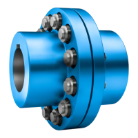
The RUPEX coupling transmits torque through pins and elastic buffers. The pins are inserted into the coupling hubs, and the elastic buffers are placed around the pins. When torque is applied, the pins engage with the buffers, transmitting power while accommodating misalignments and damping shocks and vibrations. The design allows for easy assembly and disassembly.
The coupling is available in different types:
- RWN type: Dimension drawing and technical data are provided for various sizes, including maximum bore, speed (rpm), and weight.
- RWS type: Similar to RWN, with specific dimension drawings and technical data.
- RFN type: Features a different dimension drawing and technical data, including additional parameters like FB, DFN, L1, DFK, and DFB.
- RFS type: Similar to RFN, with its own dimension drawing and technical data.
Important Technical Specifications
- Maximum Permissible Torsional Backlash: The maximum permissible torsional backlash varies depending on the coupling size. For sizes 105-500, values range from 3.0 mm to 8.5 mm. For sizes 560-2000, values range from 10.0 mm to 20.0 mm.
- Shaft Misalignment Values: The maximum permissible shaft misalignment values (axial, angular, and radial) are specified for different coupling speeds (rpm). For example, at 250 rpm, axial misalignment (ΔKa) ranges from 0.35 to 1.25, angular misalignment (ΔKw) from 0.1 to 0.5, and radial misalignment (ΔKr) from 0.1 to 0.45. These values decrease as the coupling speed increases.
- Tightening Torques: Specific tightening torques (TA) are provided for bolt connections and coupling part 20 to the mating part, varying by bolt size and coupling size. For instance, for coupling size 105, the tightening torque for bolt connection is 8 Nm, and for coupling part 20, it is 25 Nm.
- Buffers: The buffers are available in different materials (NBR, NR, HNBR) and hardnesses (80 Shore A, 65 Shore A, 90 Shore A). They are designed for various ambient temperatures and are approved for specific explosion groups (IIA, IIB, IIC). Some buffers are special for shifting resonant speed or electrically insulating.
- Maximum Surface Temperature (TX): For explosive atmospheres, the maximum surface temperature is specified based on the maximum ambient temperature. For gases, vapours, or mists, at 80 °C ambient, the TX class is T4. For dust/air mixtures, at 80 °C ambient, the maximum surface temperature is 110 °C.
Usage Features
- Intended Use: The coupling is intended for use under normal operating conditions. It can be used in potentially explosive atmospheres, provided the specific safety instructions are followed. Only original replacement parts from Flender are allowed.
- Assembly: The assembly process involves preparatory work, milling the finished bore, milling the parallel keyway, machining an axial locking mechanism, and balancing the coupling. Detailed instructions are provided for each step, including recommended assigned fits for bores with parallel key connection (e.g., j6, h6, k6, m6, n6, H7).
- Alignment: Proper alignment is crucial for optimal performance and longevity. The manual provides guidelines for aligning the coupling, including axial, angular, and radial misalignment values.
- Commissioning: Before commissioning, it is essential to perform safety checks, including ensuring no igniting deposits are present and verifying the coupling is free from damage. Tests and rotational direction checks should be performed.
- Operation: Normal operation involves continuous monitoring for unusual coupling noise or sudden occurrences of shocks. In case of faults, the manual provides a troubleshooting guide to identify causes and rectification measures.
- Transport and Storage: The coupling should be transported carefully to prevent damage. For storage, it should be kept in a dry, condensation-free room. Long-term storage requires specific preservative agents and regular inspection.
Maintenance Features
- Maintenance Intervals: Regular maintenance is essential. Initial maintenance is recommended after 3 months of commissioning, followed by follow-up maintenance every 12 months.
- Replacing Wearing Parts: The buffers are wearing parts and need to be replaced periodically. The manual provides detailed instructions for replacing buffers of different sizes (400, 450-630, 710) and for removing and pressing out bolts.
- Correcting Faults: The manual includes a comprehensive section on identifying and correcting faults, such as sudden changes in noise level, shifted alignment, unsuitable coupling, incorrect assembly, and maintenance-related issues.
- Removing Coupling Parts: Instructions are provided for removing coupling part 1 (1), 2 (2), or 20 (20) with shaft and hub connected by a parallel key or by a pressurised oil interference fit, and with flange connection. This includes steps for disassembling the machines, removing buffers, and handling oil pressure.
- Spare Parts: When ordering spare parts, it is crucial to use original Flender parts. Information required for ordering includes the Flender order number, drawing number, coupling type and size, part number, and dimensions. A list of spare parts with their designations is provided.