L 1506 VR, LG 1704 VR
21
Screw the clamping nut with flange face
up, onto the spindle.
Press and hold down the spindle lock.
Tighten the clamping nut with the stop
key.
Insert the mains plug into the socket.
Switch on the power tool (without locking
the button) and leave it running for
approx. 30 seconds. Check for
imbalances and vibrations.
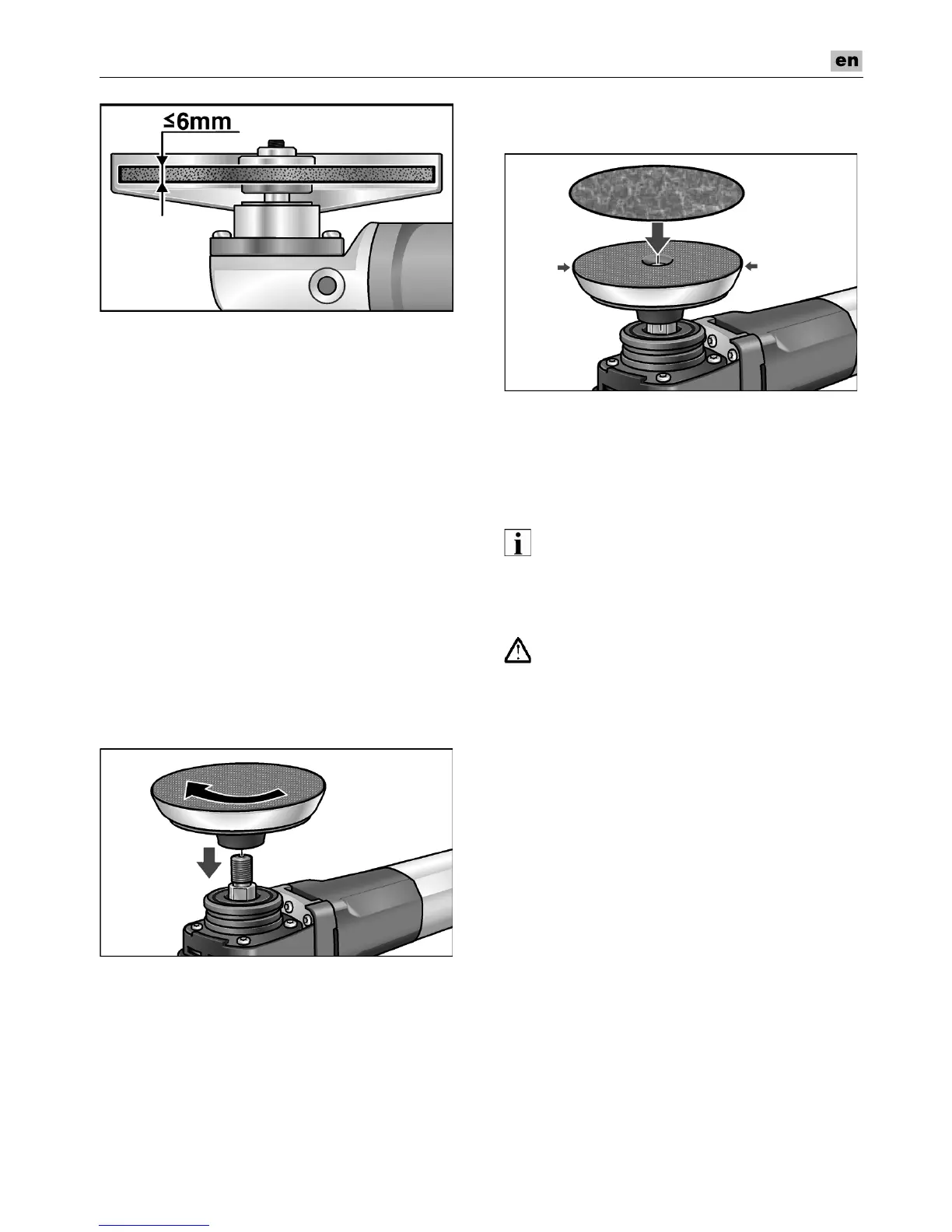
Attaching the Velcro pad
Pull out the mains plug.
Remove quick-change guard.
Press and hold down the spindle lock.
Using the stop key, loosen the clamping
nut on the spindle in an anti-clockwise
direction and remove.
Remove clamping flange.
Screw Velcro pad clockwise onto the
spindle and tighten hand-tight.
Attaching or changing sandpaper
Pull out the mains plug.
Place the sandpaper in the centre of the
Velcro pad and press on.
Carry out a test run to check that the tool
is clamped in the centre.
Operating instructions
klqb
tÜÉå=íÜÉ=éçïÉê=íççä=áë=ëïáíÅÜÉÇ=çÑÑI=íÜÉ=íççä=
ÅçåíáåìÉë=êìååáåÖ=ÄêáÉÑäóK
Rough-grinding
t^okfkd>
kÉîÉê=ìëÉ=ÅìííáåÖJçÑÑ=ïÜÉÉäë=Ñçê=êçìÖÜJ
ÖêáåÇáåÖK
– Angle of wheel 20–40° for best cutting
performance.
– Move the power tool to and fro, applying
moderate pressure. As a result, the
workpiece will not become too hot and
there will be no discoloration; nor will
there be any grooves.

 Loading...