This document outlines the procedure for swapping the Micro SD card in FlexRadio FLEX-6400/6600 Series radios, providing detailed, step-by-step instructions for maintenance.
Function Description:
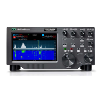
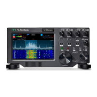
The FlexRadio FLEX-6400/6600 Series radios are software-defined radios (SDRs) designed for amateur radio enthusiasts. These devices offer advanced features for radio communication, including a SmartSDR interface for intuitive control and operation. The Micro SD card serves as a critical component, likely storing the radio's operating system, firmware, and potentially user configurations, enabling the radio to boot up and function correctly. The process described in this manual is a maintenance procedure to replace this essential component, ensuring the continued operation or upgrading of the radio's core software.
Important Technical Specifications (Inferred from the manual):
- Micro SD Card: The radio utilizes a Micro SD card, with an example showing a "Micro 256MB INDUSTRIAL DELKIN DEVICES" card, suggesting that specific industrial-grade or high-reliability cards might be recommended or required for optimal performance and longevity. The capacity of 256MB indicates that the primary function of the card is likely for system files rather than extensive data storage.
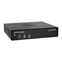
- Power Input: The radio requires a 13.8V DC input for operation, which is a standard power requirement for many amateur radio transceivers.
- Connectivity: The radio supports Ethernet connectivity, which is crucial for network integration, SmartSDR operation, and potentially firmware updates.
- Torx Screws: The enclosure is secured with T8 Torx screws, indicating a specific tool requirement for disassembly and reassembly.
- CPU Board: The Micro SD card is located on the CPU board, highlighting its integral role in the radio's processing and control functions.
Usage Features:
- SmartSDR Interface: The radio operates with SmartSDR software, providing a user-friendly interface for controlling radio functions. This software-defined approach allows for flexible and customizable operation.
- Power LED Indicator: A solid green Power LED indicates that the radio has successfully booted and is operational, providing immediate visual feedback on the system status.
- Front Panel Controls: The radio features a comprehensive front panel with various knobs and buttons for direct control over functions such as AF/RF gain, band selection, mode, ATU (Antenna Tuning Unit), MOX (Manual Operate/Transmit), TUNE, and SQL (Squelch). A display screen is also present for visual feedback and menu navigation.
- SmartLink Setup: The interface includes options for "SmartLink Setup," suggesting advanced networking capabilities for remote operation or integration with other FlexRadio systems.
Maintenance Features:
- Micro SD Card Swap: The primary maintenance feature detailed is the replacement of the Micro SD card. This procedure is critical for addressing potential issues with the existing card, upgrading to a new version of the operating system, or restoring functionality.
- Kapton Tape: The use of Kapton tape over the Micro SD card connector assembly suggests a protective measure, likely to secure the card in place, prevent accidental dislodgement, and potentially offer insulation or environmental protection. Replacing this tape is part of the reassembly process.
- Careful Disassembly/Reassembly: The instructions emphasize careful handling of the top cover to avoid scratching or denting, and caution against overtightening screws during reassembly. This highlights the precision required for maintaining the device's physical integrity.
- Troubleshooting (Boot Failure): The manual provides a basic troubleshooting step: if the radio does not boot after a card swap, power down, reseat the Micro SD card, and try again. This indicates that proper seating of the card is crucial for successful operation.
- Tool Requirement: The need for a T8 Torx wrench for disassembly and reassembly specifies the necessary tool for performing the maintenance.
- Component Identification: The manual includes images with numbered labels to clearly identify screws, the Micro SD card location, and other relevant components, simplifying the maintenance process for the user.
- Sequential Steps: The maintenance process is broken down into clear, sequential steps, making it easy to follow even for users who may not be highly experienced with electronics repair. Each step is accompanied by visual aids.
- Handling Precautions: Notes such as "Handle cover with care to avoid accidental scratching or denting" and "Be careful not to overtighten screws" are provided to guide the user in performing the maintenance without causing further damage to the device.
- Verification Step: After the card swap and reassembly, a verification step is included to ensure the radio boots correctly and the Power LED is solid green, confirming the success of the maintenance operation.