Do you have a question about the FlexRadio FLEX-6600 and is the answer not in the manual?
Carefully remove the top cover by removing the 4 screws on top and 5 screws from each side with a T8 Torx.
Locate the Micro SD card on the CPU board.
Remove Kapton tape from the Micro SD card connector assembly.
Slide the connector latch to open, rotate 180 degrees, and remove the old Micro SD card.
Install the new Micro SD card flush against the connector and close the latch.
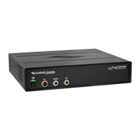
Connect the 13.8V DC input and the Ethernet cable.
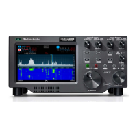
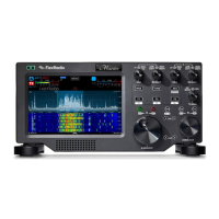
Turn the radio on and verify it boots fully on SmartSDR with a solid green Power LED.
Power off the radio, allow it to fully power off, then disconnect cables.
Install a new piece of Kapton tape over the Micro SD card connector assembly.
Carefully reinstall the top cover and install the 4 top screws and 5 side screws with a T8 Torx.
| Receiver Type | Direct Sampling |
|---|---|
| Transmitter Power | 100 W |
| Type | Software Defined Radio |
| Frequency Range | 30 kHz – 54 MHz |
| Modes | SSB, CW, AM, FM, Digital |
| Number of Receivers | 4 |
| Connectivity | Ethernet |
| Interfaces | Ethernet, USB, Microphone, Headphone, Speaker |
| Power Requirements | 13.8 VDC |
| Display Type | External Display Required |
| ADC Resolution | 16 bits |