FAA-27, Technical Manual, Rev. 1.1, June 2014
5. Adjustments
5.1 Adjustment with Rotary Switches
To start the adjustment the programming switch should be at analog output type
position, V or I.
Z and G positions of the programming switch are used for performing zero and gain
adjustments in sequence. Analog output is changed by turning the adjustment switch
as described in the table below.
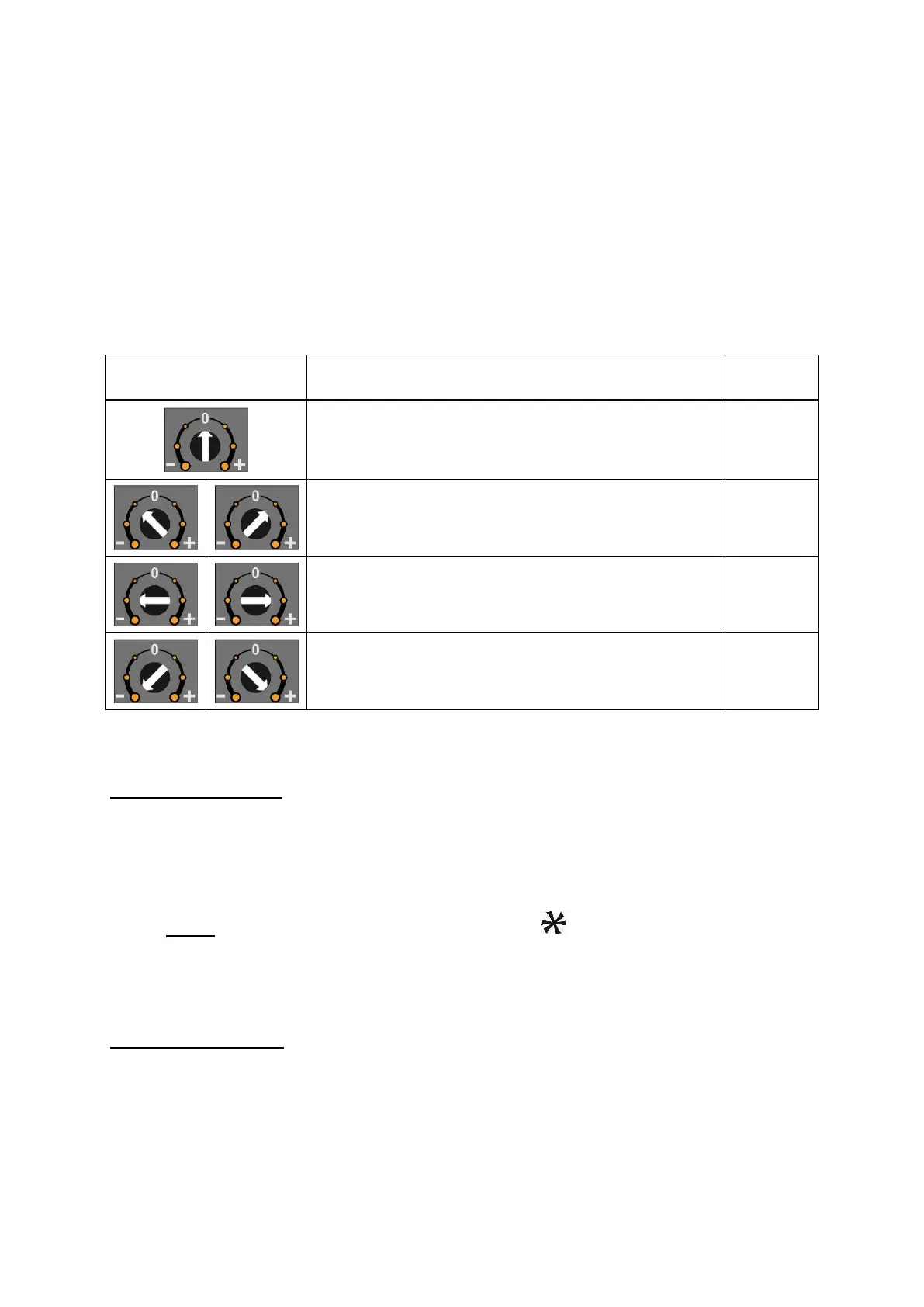
Adjustment rotary
switch position
Rotary switch description
Decrease ( - ) / Increase ( + ) in slow steps
Decrease ( - ) / Increase ( + ) in medium steps
Decrease ( - ) / Increase ( + ) in big steps
RUN LED flashes to indicate the instrument is not in operation.
Zero Adjustment
Connect the measurement instrument to the analog output.
Unload the scale.
Turn the programming switch to the Z position from the analog output type
position.
Increase or decrease the analog output by adjustment rotary switch.
Never bring the adjustment switch position to position in this adjustment.
The adjustment switch must be at 0 - position at the end of the adjustment.
Turn the programming switch to analog output type position (V or I) to start the
operation or to the G position to start gain adjustment.
Gain Adjustment
Connect the measurement instrument to the analog output.
Load the scale.
The analog output value should be calculated for the applied load.