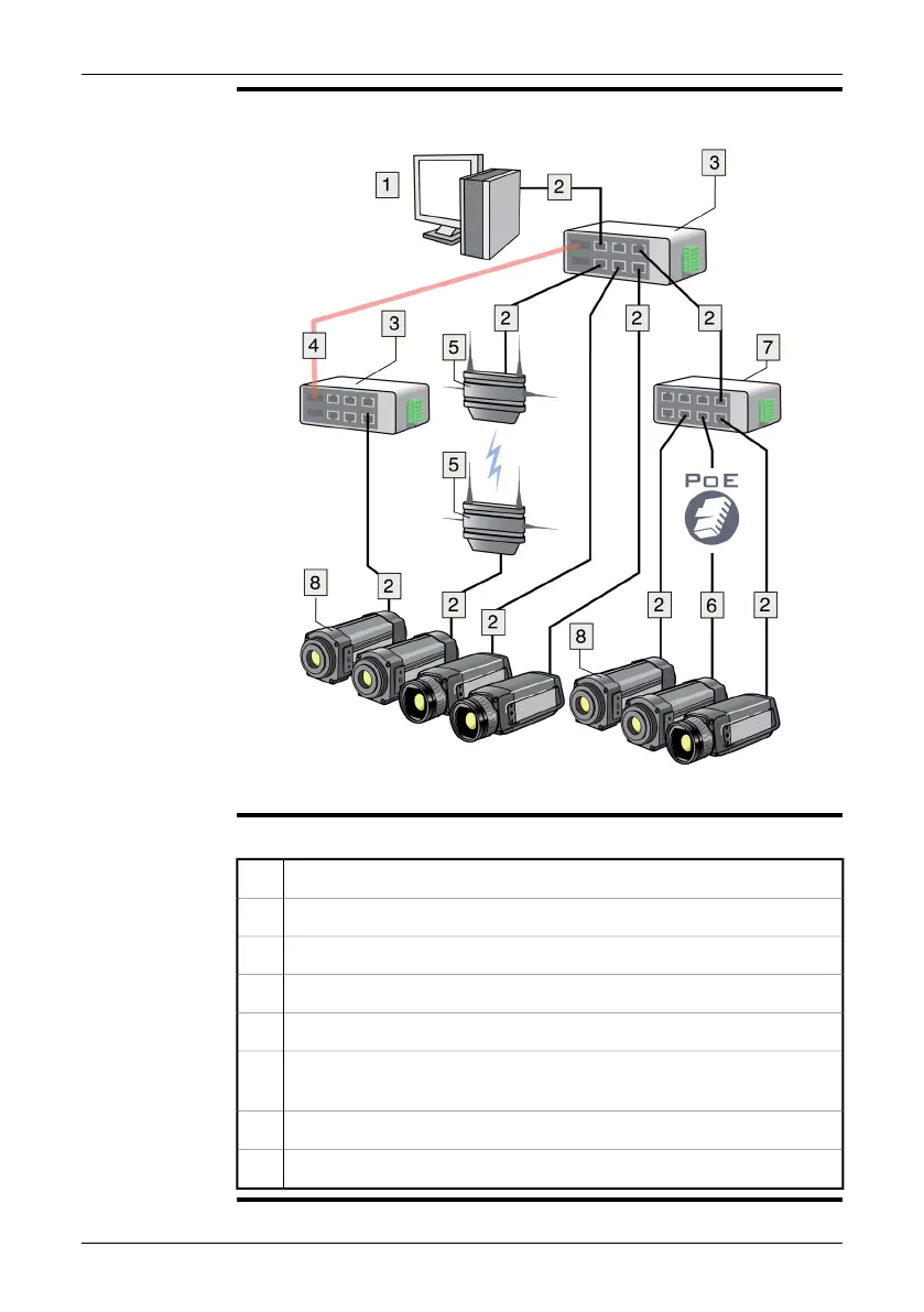
Figure
10777603;a4
Explanation
This table explains the figure:
Computer1
CAT-6 Ethernet™ cable with RJ45 connectors2
Industrial Ethernet™ switches with fiber optic ports3
Fiber optic cable4
Wireless access points5
CAT-6 Ethernet™ cable with RJ45 connectors—powering the camera using
PoE (Power over Ethernet™, dependent on the camera model)
6
Industrial Ethernet™ switch7
FLIR A3XX/A6XX cameras8
28 Publ. No. T559498 Rev. a461 – ENGLISH (EN) – August 19, 2010
11 – Example system overviews
 Loading...