Connectors, controls, and
indicators
9
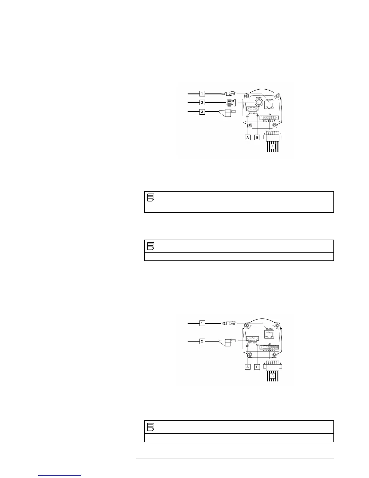
9.1 FLIR A3xx series
9.2 Explanation
1. Network cable with an RJ45 connector for Ethernet connectivity and Power over
Ethernet (PoE) (dependent on the camera model)
NOTE
Only CAT-6 Ethernet cables should be used with this camera.
2. Video cable with a BNC connector for CVBS (composite video) output (dependent
on the camera model).
3. Power cable for 12–24 V DC power in.
NOTE
The power connector on the camera is polarity protected.
4. Digital I/O ports, opto-isolated (six-pole screw terminal).
A.Power indicator.
B.Hardware reset button (for a factory default reset).
Use an unbent paper clip or a similar tool to press the reset button through the small
hole on the back of the camera for 5 seconds, then release the button.
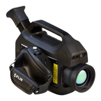
9.3 FLIR A3xx sc series
9.4 Explanation
1. Network cable with an RJ45 connector for Ethernet connectivity and PoE (dependent
on the camera model).
NOTE
Only CAT-6 Ethernet cables should be used with this camera.
#T559498; r.22370/22370; en-US
16