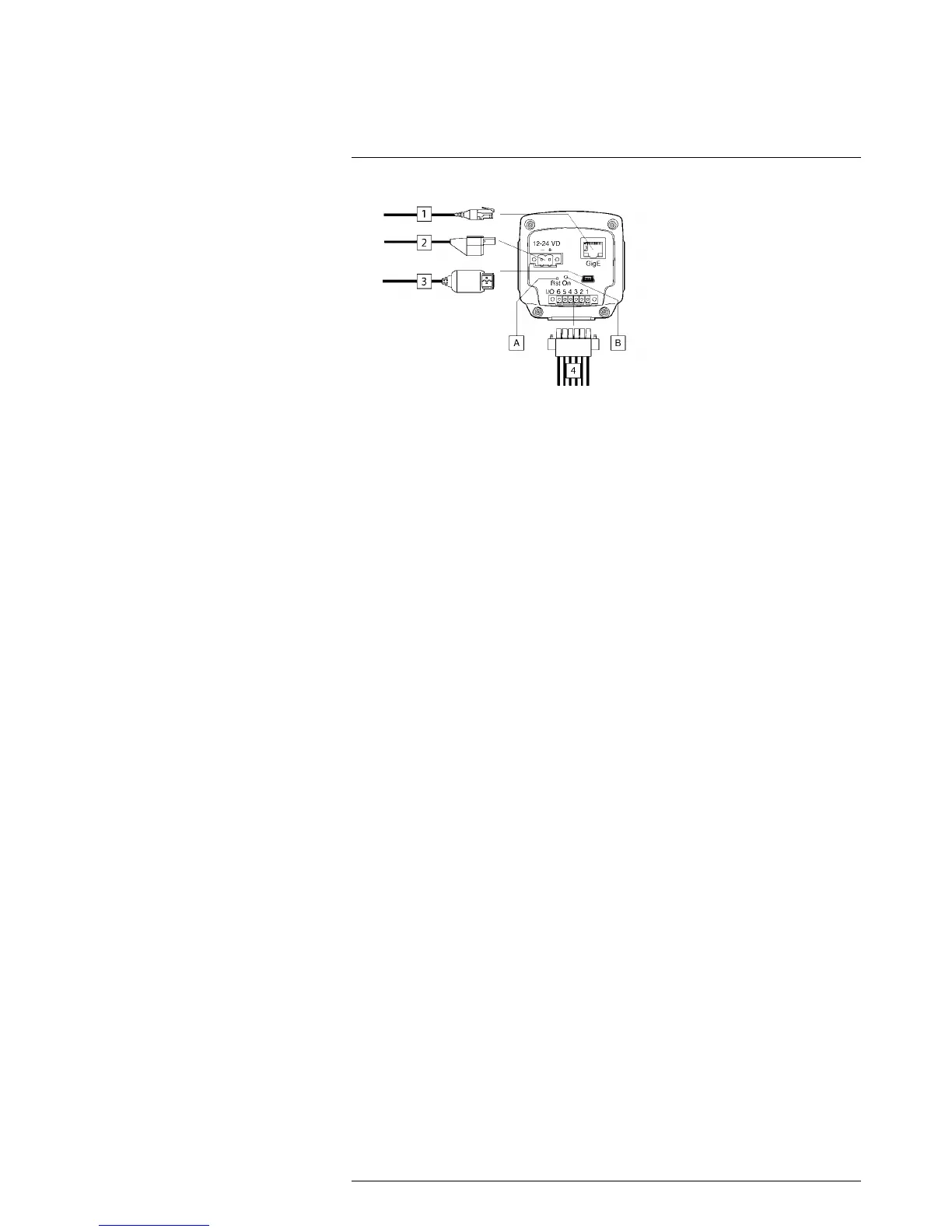
11.1 Explanation
1. Network cable with an RJ45 connector for Ethernet connectivity and Power over
Ethernet (PoE) (dependent on the camera model).
Note Only CAT-6 Ethernet cables should be used with this camera.
2. Power cable for 12–24 V DC power in.
Note The power connector on the camera is polarity protected.
3. USB cable with a USB mini-B connector for control and image transfer.
4. Digital I/O ports, opto-isolated (six-pole screw terminal).
A. Hardware reset button (for a factory default reset).
Use a straightened paper clip or a similar tool to press the reset button through the
small hole on the back of the camera for 5 seconds, then release the button.
B. Power indicator.