427-0073-12-12 Version 120 May 2015 3-25
3
Advanced Configuration
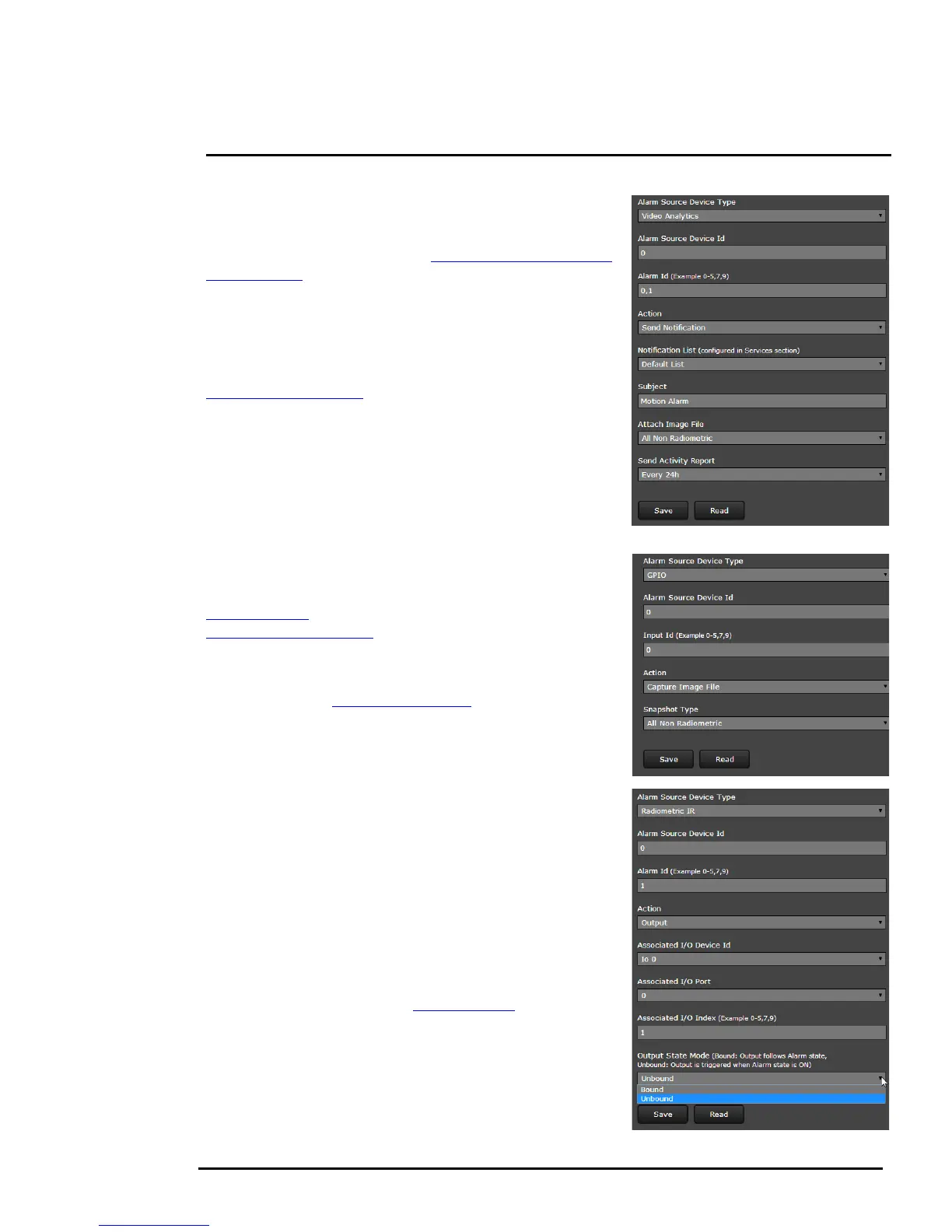
Video Analytics Alarm to Email: Shown at the right is an
example of an alarm rule that causes an email notification
(with a snapshot image) to be sent when a motion alarm
occurs in VA Area 0 or 1 (refer to Creating Motion Detection
Areas, pg. 3-5).
The Alarm Source Device Type is set to Video Analytics
with Alarm Id set to “0,1” corresponding to VA Areas 0 and 1.
The Send Notification action uses a Msg System and a
Notification List that are set up in the Services menu (refer to
Msg Systems, pg. 2-13). The email includes alarm
information, including the Area ID and if it is a human or
vehicle alarm. When an email is sent, the Alarm Manager
can attach a snapshot from the camera to the email. In
Attach Image File, All Non Radiometric is selected for the
type of image since the alarm type is Analytics (a
radiometric image can be sent if the alarm type is
Radiometric IR).
GPIO Input to Snapshot: In the example rule shown at the
right the source type of the alarm is GPIO, with the Input ID
set to 0, which corresponds with the input IO 0 (refer to
GPIO, pg. 3-17), then takes a snapshot and stores it in the
Media Browser, pg. 3-27.
The Action is set to Capture Image File, and that causes a
snapshot to be saved in the Media Browser folder when the
alarm occurs (see Files Menu, pg. 3-26). The Snapshot type
can be set to All Non Radiometric (a normal JPEG image),
Radiometric (a special type of JPEG with temperature
data), or All (saves both types).
Radiometric IR Alarm to GPIO Output:
The final
example shows an alarm rule that causes a GPIO output
when a temperature alarm is detected. The source Alarm Id
set to 1 corresponds to area number 1 on the Radiometry
Setup page (for example, 1:SCR_SPOT).
Note: the Associated I/O Port is set to 0, and the Associated
I/O Index is set to 1 (this corresponds with the output IO 1).
The GPIO Output State Mode can be set as Bound or
Unbound. If Bound, the output turns on when an alarm
occurs and turns off when the alarm is cleared or the Output
Reset Interval is reached (see GPIO, pg. 3-17).
If Unbound, the output turns on when an alarm occurs and
remains on until it is reset by the Output Reset Interval time-
out or by a command from the network (for example, from
FSM using the IO Advanced Sensors Contol panel).

 Loading...