427-0073-12-28 Rev 100 May 2014
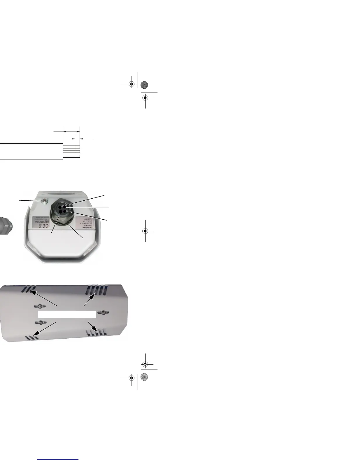
Step 1 Remove cover: Using 3 mm hex key, loosen four captive
screws. Removal of sunshield not necessary.
Step 2 Install cables through sealing gland:
Step 3 If using conventional power cable, strip cable as described
below:
Access captive screws
through slots in sunshield.
Video coax
Gland nut
Ethernet
Accessory
Power cable
Ground
Re-tighten gland nut after
installation is completed.
Fill any unused hole with
orange plug.
427-0073-12-28 Rev 100 May 2014
Step 4 Ter m i n a te ca b l e s :
Caution!
Connection Purpose
1 3-pin Jumper Lens heater on/off
2RCA Analog video test point
3BNC Analog video
43-pin Terminal AC/DC Power
5 Ethernet PoE power, communications, IP video stream
6 6-pin terminal J8 General purpose I/O (GPIO)
7 Reserved for future use Do not connect
Ta b l e 1 - 1: Powe r Co n n ec t o r
1Chassis
2Vac/dc -
3Vac/dc +
Table 1-2: GPIO Connections - J8
Pin Connection Pin Connection
1 Chassis ground 4
GPIO In
(digital ground)
2 GPIO Out 5 GPIO In (+5V)
3 GPIO Out 6 Chassis ground
Pins 4 and 5 should not be connected to any voltages or power sources outside
the camera. Damage to the camera may result.

 Loading...