5
Remote IR MonitoringChapter
Remote IR Monitoring
Overview
Infrared radiation is emitted by all objects
at temperatures above absolute zero
and is detectable by IR cameras. Since
these cameras have various means of
communicating thermographic images
and temperatures to remote locations,
they are ideal for remote and unattended
monitoring. Moreover, smart IR cameras
(those with built-in logic, analytics, and
data communications), can compare
the temperatures obtained from their
thermographic images with user-dened
settings. This allows the camera to
output a digital signal for alarm and
control purposes, while also providing
live images.
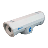
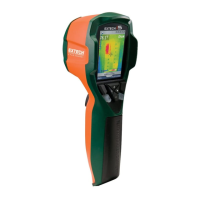
IR Camera Operation
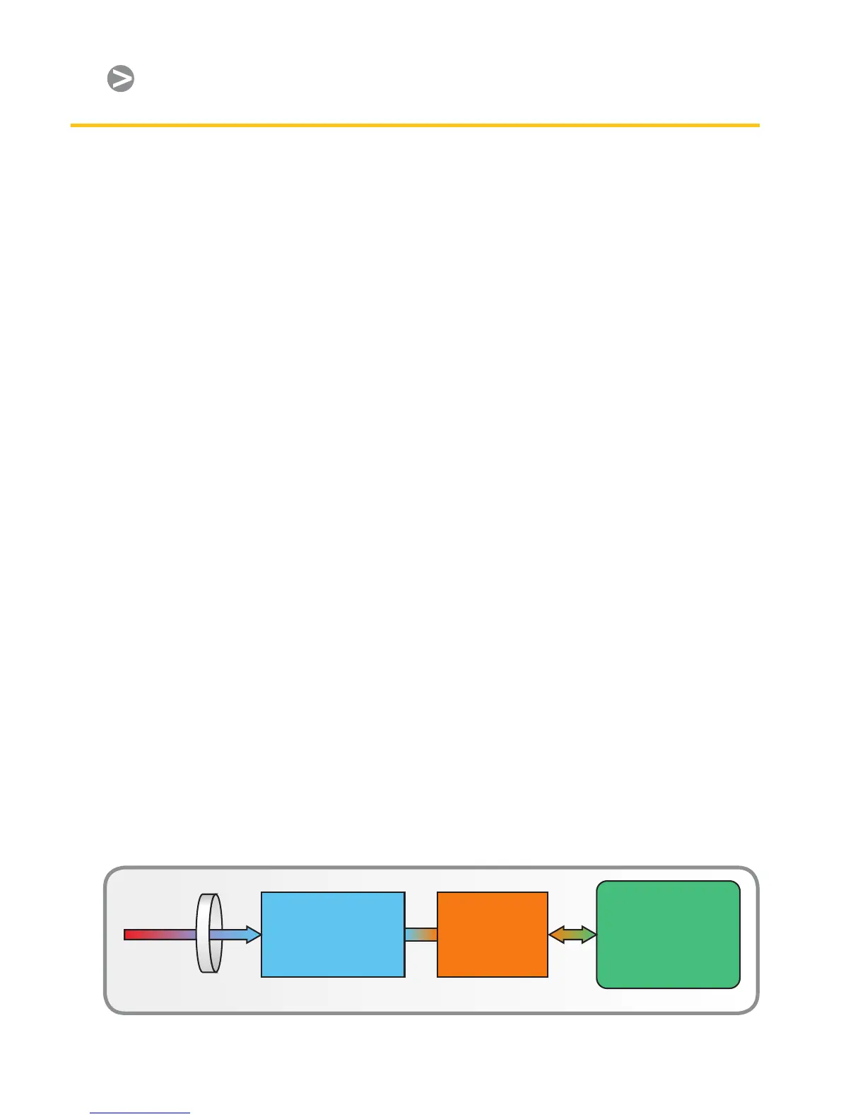
IR camera construction is similar to
a digital video camera. The main
components are a lens that focuses IR
onto a detector, plus electronics and
software for processing and displaying
thermographic images and temperatures
on an LCD or CRT monitor (Figure 1).
Instead of a charge coupled device
that video and digital still cameras use,
the IR camera detector is a focal plane
array (FPA) of micrometer size pixels
made of various materials sensitive to
IR wavelengths. FPA resolution ranges
from about 80×80 pixels up to 1024×1024
pixels. In some IR cameras, the video
processing electronics include the logic
and analytical functions mentioned
earlier. Camera rmware allows the
user to focus on a specic area of the
FPA or use the entire detector area
for calculating minimum, maximum,
and average temperatures. Typically,
temperature measurement precision is
±°C or better.
The camera lens and distance to the
target object results in a eld of view
(FOV) that determines the spot size
covered by each pixel. The pixel’s analog
output represents the intensity of heat
energy received from the spot it covers
on the target object. In FLIR IR cameras,
the A/D converters that digitize the pixel
output have resolutions that range from
8 bits (2
8
or 0–255 pixels) up to 14 bits
(2
14
or 0–16383 pixels). The thermographic
image seen on the monitor screen is
the result of a microprocessor mapping
these pixel output values to a color or
gray scale scheme representing relative
temperatures. In addition, radiometric
information associated with the heat
energy impinging on a pixel is stored
for use in calculating the precise
temperature of the spot covered by
that pixel.