54
Appendix C
This last relation is a particularly
convenient one, because it is often easier
to measure reectance than to measure
emissivity directly.
The Measurement Formula
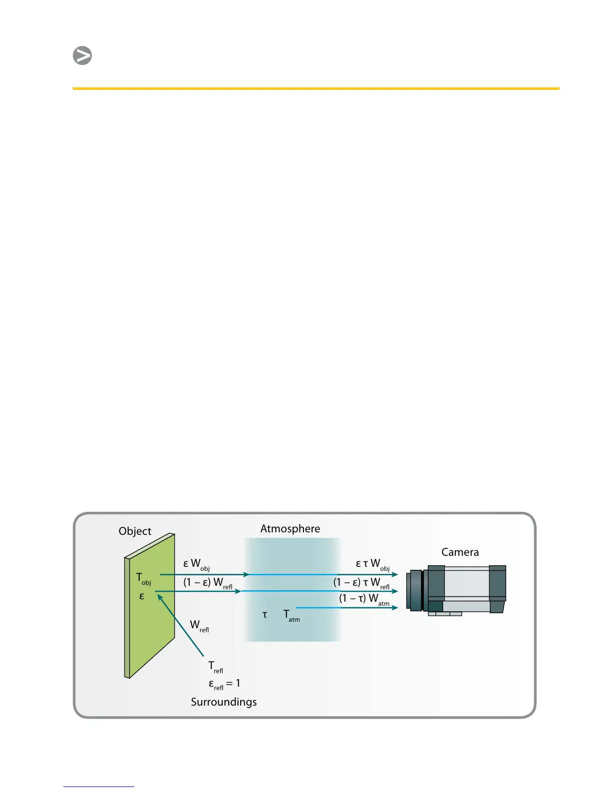
As already mentioned, when viewing
an object, the camera receives radiation
not only from the object itself, it also
collects radiation from the surroundings
reected via the object surface. Both
these radiation contributions become
attenuated to some extent by the
atmosphere in the measurement path. To
this comes a third radiation contribution
from the atmosphere itself.
This description of the measurement
situation, as illustrated in Figure 14, is so
far a fairly true description of the real
conditions. What has been neglected
could for instance be sun light scattering
in the atmosphere or stray radiation from
intense radiation sources outside the eld
of view. Such disturbances are dicult
to quantify. However, in most cases
they are fortunately small enough to be
neglected. In case they are not negligible,
the measurement conguration is likely
to be such that the risk for disturbance
is obvious, at least to a trained operator.
It is then his responsibility to modify
the measurement situation to avoid the
disturbance (by changing the viewing
direction, shielding o intense radiation
sources, etc.).
Accepting the description above, we can
use Figure 14 to derive a formula for the
calculation of the object temperature
from the calibrated camera output.
Assume that the received radiation
power W from a blackbody source of
temperature T
source
on short distances
generates a camera output signal U
source
that is proportional to the power input
(power linear camera). We can then write
(Equation 1):
U
source
= CW (T
source
)
or, with simplied notation:
U
source
= CW
source
where C is a constant.
Figure 14. A schematic representation of the general thermographic measurement situation.