7
Remote IR Monitoring
While visible light cameras might be
used in such an application, there often
is a line-of-sight problem where many
of the barrels cannot be seen, even with
multiple cameras positioned throughout
the storage area. In addition, smoke or
ames would have to be present before
a visible light camera could detect a
problem. This might be too late for
preventative measures to be taken.
In contrast, stand-alone IR cameras
monitoring the facility can detect a
temperature rise within their FOV before
re occurs (Figures 2a and 2b).
Depending on the camera manufacturer,
several monitoring options are available.
For instance, the FLIR A320 camera
allows a threshold temperature value to
be set internally for alarm purposes. In
addition, the camera’s logic and clock
functions can be congured so that a rise
in temperature must be maintained for a
certain period of time before an alarm is
sent. This allows the system to ignore a
temporary temperature rise in a camera’s
FOV caused by a forklift entering the area
to add or remove barrels. Furthermore,
a hysteresis function can also be used to
prevent an alarm from turning o until
the detected temperature falls well below
the setpoint (Figure 3).
Cameras with a digital I/O interface
typically provide an OFF/ON type of
output for alarm purposes. The digital
I/O output is either o or on; when on, it
is typically a DC voltage or current. For
example, the digital I/O output from a
FLIR A320 camera is 10–30VDC for loads
of 100mA or less. Typically, the digital
I/O output is sent to a PLC (Programble
Logic Controller) that controls the portion
of an alarm system associated with the
monitored area.
A good way to set up the alarm system
is to have all cameras congured so they
have a high level digital output when the
temperature is below the alarm condition
that holds a PLC in its non-alarm state.
When the alarm setpoint temperature is
detected, the camera’s digital I/O output
goes low (typically zero volts) after an
appropriate time delay, causing the PLC
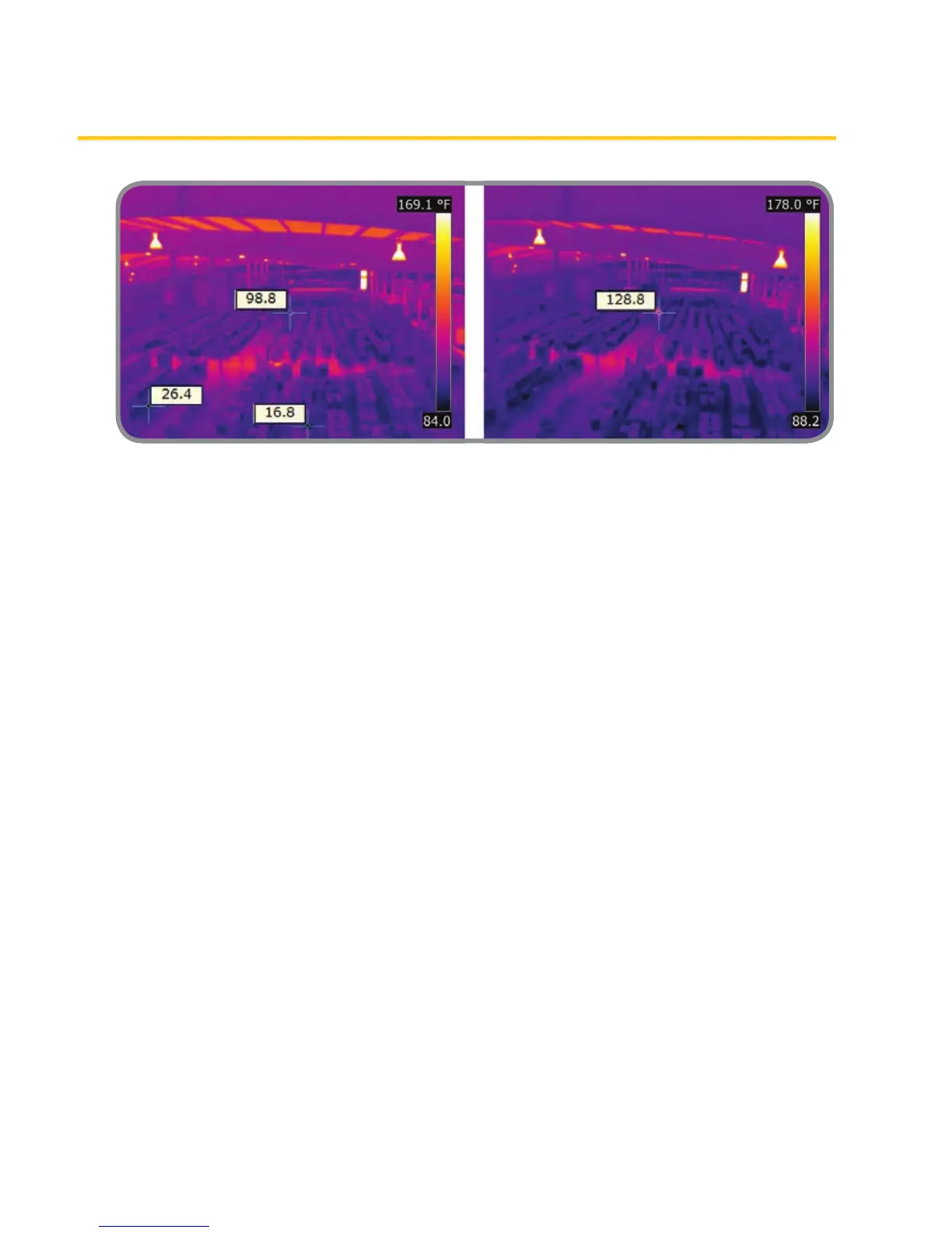
Figure 2a. IR image of a hazardous waste storage
area showing two spot temperature readings
(26.4°F and 16.8°F) that are in the safe range, plus
one reading (98.8°F) that is abnormally high.
Figure 2b. A subsequent image of the same
area shows that the abnormal reading in 2a
has increased further, causing an alarm to
go o.