37
Real-Time Control Issues
camera rmware nds the minimum and
maximum temperatures and calculates
the average temperature inside the
area selected. Clearly, more processing
time is required for area measurements,
particularly if multiple areas are selected.
This also means that more data is being
transmitted over a machine vision
system’s communications network, along
with more latency.
Emissivity Calibration. Earlier, it was
pointed out that accurate temperature
measurements on a specic object
require the emissivity value for that
object. In eect, this adjusts the factory
calibration that is based on a perfect
blackbody having an emissivity value of
1.0. This adjustment consumes processor
time. To avoid this, the FLIR A325 uses a
global emissivity value (input by the user)
for the camera’s entire FOV. Normally,
this isn’t a problem for machine vision
applications and it avoids the time
required to apply non-global emissivity
values on the y. Instead, the application
program is set up to make decisions
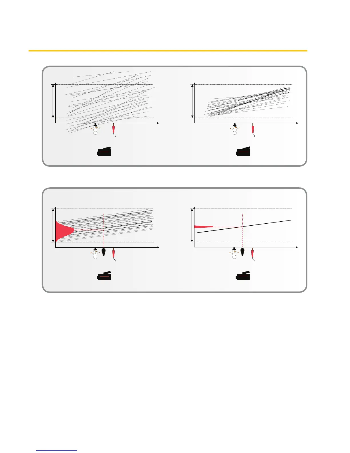
Figure 6b. Final steps in IR camera’s NUC process